Deep Dive into the EZVIZ DB1 Doorbell with Home Assistant
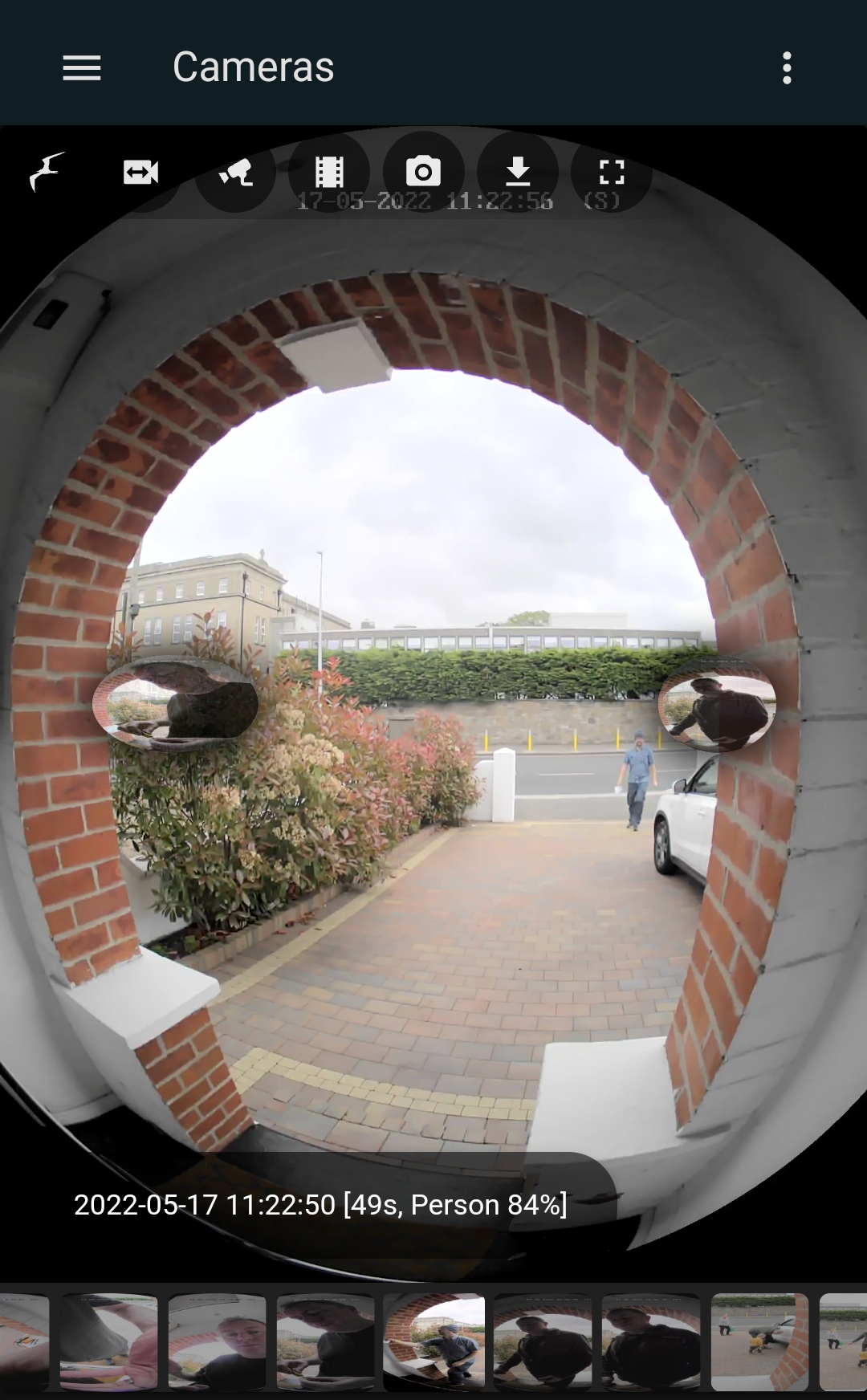
I’m on a mission to rid my house of Cloud dependencies and recently replaced my Google Nest doorbell with an EZVIZ DB1 (also known as the Hikvision DS-HD1). The DB1 has higher specs than the Nest or Ring, but a more open design. It is highly configurable, has a locally-accessible ONVIF API and can be streamed over RTSP. It has an ONVIF-enabled PIR motion sensor as well as video motion sensor, and when someone presses the button you receive a peer-to-peer video VoIP call to your phone. Unfortunately, unlocking all this functionality was not straightforward. The journey had some twists, turns and dead ends. Here’s a detailed write up of how I got it fully and reliably working in all its glory.
This is the second post in a series about the EZVIZ DB1 smart doorbell. Also see Improving the DB1 Doorbell and Making a New EZVIZ DB1 Button.
The best smart doorbell?
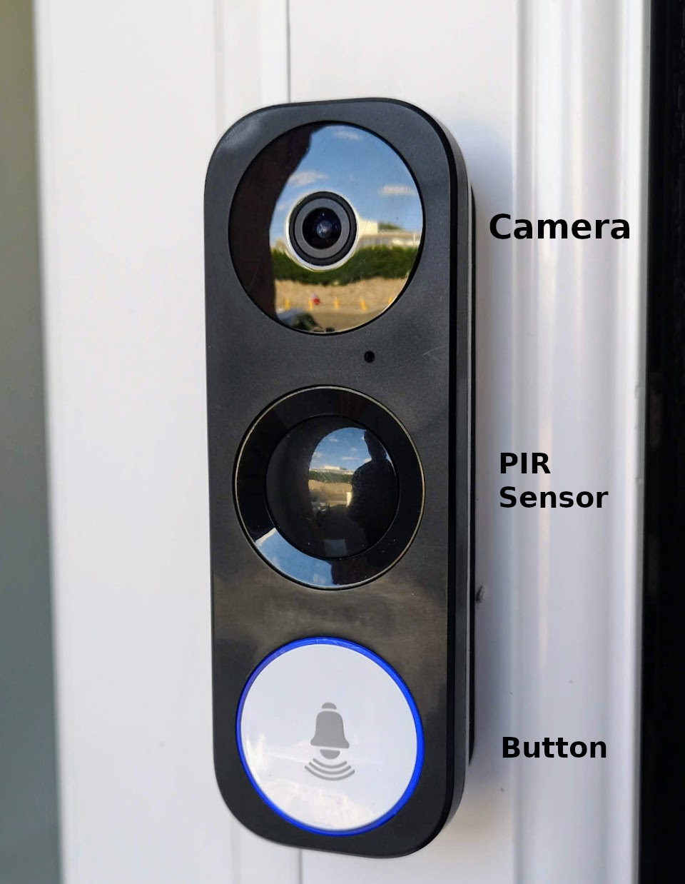
The EZVIZ DB1 should not be confused with any of the other similarly named products from EZVIZ. The DB1 Pro, DB1C, DB2, and DB2 Pro are completely different devices. EZVIZ is a sub-brand of HikVision, and the DB1 is actually a rebadged Hikvision DS-HD1, and is also sold as the RCA HSDB2A, LaView LV-PDB1630-U, Nelly’s NSC-DB2 and LTS LTH-7132-WIFI. It has mostly equivalent specs to the wired Nest doorbell, except for an improved resolution of 2048x1536 pixels (vs Nest’s 1600x1200), and a greater 180° vertical field of view (vs 160°), which means you can see parcels left on the ground. It’s the only smart doorbell I’ve come across that has an integrated PIR sensor, which is more reliable for person detection than video motion detection (and more reliable than AI person detection so long as its not facing a public footpath). It is also nearly half the price of the wired Google Nest doorbell.
The closest popular alternative devices are the Nest Doorbell (Wired) and the Ring Pro 2, which in my experience were reasonably good cloud-based cameras but useless doorbells that caused me to regularly miss callers to the house, with multi-second audio lag if I tried to talk to anyone at the door using their apps. In contrast, the DB1 has the potential to be both a great camera and a great smart doorbell.
Pros
- Low-latency local RTSP camera stream, allowing it to be viewed with near zero lag, and integrated with Network Video Recorders (NVRs) like Frigate, BlueIris, and MotionEye.
- Motion events (both video and PIR) are accessible via local ONVIF API.
- Excellent image resolution that beats competing doorbells.
- Its uniquely high vertical field of view produces an image with a natural portrait orientation, which is excellent for seeing the ground below the doorbell as well as the person in front of it. In other words, you can see parcels left on the ground.
- Excellent configurability as a camera.
- You see and hear callers via a peer-to-peer video connection, producing optimal performance and minimal lag, and eliminating the variability of routing and processing the video stream via underprovisioned or flakey cloud servers (I have rarely managed to be able to hold a conversation with a caller using my Ring or Nest doorbells)
- No delayed notifications that result in missed callers (looking at you, Google and Amazon)
- As a wired doorbell it has a constant power supply.
- No battery means a relatively small form factor, comparable with Nest Wired doorbell.
- You can add a MicroSD card to record recent events callers and motion events, which are then available in-app.
- No subscription. There is no cloud service involved in using this device, which means no monthly fees.
- Because there is no dependency on cloud services for its core operation, the device is safe from planned obsolescence or having its servers turned off. (Caveat: app notifications and initiation of peer-to-peer calls require server communication).
- Cheap. It is currently priced at about €155 (or $118 on Amazon.com), versus €279 for the Nest Doorbell (wired) or the €250 for the Ring Pro 2.
Cons
- Button press events are not exposed via an API, and therefore can’t be automated against without a bit of hacking.
- The device can support only three simultanous streaming clients.
- Some visitors, from pensioners to PhDs, inexplicably press the PIR sensor instead of the button. Even with the faceplate button swapped to make it the only contrasting element in the design, some people continue to jab at the PIR sensor (and can’t even tell me why). (I finally resolved this by making a more prominent button)
- There are a confusing number of firmwares available, each of which have different pros and cons.
- There are multiple apps to choose from, none of which are perfect, and most of which are unreliable at receiving calls from the doorbell.
- Despite its main operation being local-network or peer-to-peer, it tries to open up a lot of connections to internet servers. Should I trust the Chinese state-owned Hangzhou Hikvision Digital Technology Company more or less than Google or Amazon?
I managed to resolve this list of cons to my satisfaction, leaving me with a smart doorbell that I think beats any alternative on the market. In this comprehensive post, I provide details on how I did this.
Contents
First, I need to acknowledge that I am indebted to the IPCamTalk community and their HikVision Doorbell 101 page. I wish that every super-long evergreen forum thread has someone like David L maintaining a summary that distills out the collective wisdom of the entire thread. If you are planning to buy one of these doorbells, that 101 page will be your bible.
In the sections below I discuss not just my conclusions and recommendations, but also how I arrived at each solution. You can read this post linearly, or jump to the bit you’re most interested in:
- For improving the physical look of the device and swapping button colours, see my previous post on removing the logo and swapping buttons and my follow up post on making a new, more prominent, button.
- Detecting the button being pressed
- Choosing a desktop configuration tool, and how to use it
- Choosing and changing the firmware
- Choosing a mobile app to use
- Integrating with Home Assistant
- Security Analysis
- Dissecting the Firmware
Detecting button presses
This device’s biggest flaw is that button presses are not exposed via any API. It’s an incredible omission. If the button was exposed via ONVIF, life would have been much easier (but much less interesting 🙂).
This section ended up a bit long. To jump to the conclusion and just see how I solved this with a €23 circuit, click here.
There are three broad strategies out there for detecting the button being pressed:
- Add a reed sensor to detect when the solenoid in your mechanical chime is energized.
- Monitor the doorbell wire to detect current being sent to the chime.
- Detect a tell-tale DNS query the doorbell makes when the button is pressed. Clever work by @fversteegen, documented on the Home Assistant community forum here.
The DNS solution is pretty genius and seems to be working well for people, but I don’t use Pihole, and creating a dependency between my DNS service and my doorbell just didn’t feel right. I decided I wanted a self-contained hardware solution.
If I had a mechanical chime I would probably have used a reed sensor (i.e., a regular door or window open/close sensor) to detect the bell. However, I don’t have one and I felt it would be just a little too steampunk to install an elecromechanical bell so my smart home automations would work.
The remaining solutions basically monitor the doorbell wiring to sense when the doorbell is trying to sound the chime. Frenck has documented using a $2 ESP-01S and a ESP relay module and an old phone charger to turn a dumb doorbell into a smart one. The Doorbell Modernizr seems like it was a pre-packaged version of Frenck’s project, but it is no longer sold. @gerard33 posted a tutorial on the Home Assistant forums that achieved the same thing using a Shelly 1. All these solutions boil down to the same strategy:
- Install a smart relay and a DC power supply.
- Disconnect the doorbell circuit from the AC transformer, and connect one end to the positive side of the DC supply that is powering the relay.
- Connect the other end of the doorbell circuit to the switching input of the smart relay. (Note: the Shelly 1 is basically a ESP8266 with a relay, so is very much like Frenck’s project)
- Connect the AC transformer and chime (if any) to the outputs of the relay.
When the (dumb) doorbell is pressed, the smart relay will detect voltage at its input, send an event to your automation hub, and it will connect the AC supply to the chime.
I saw two drawbacks to this approach. First, I didn’t want to install a 5V DC power supply. I preferred a solution that could be powered by the 12-24V AC power supply that was already in place (admittedly, I could have added a rectifier and resistors to convert to 5V DC at the cost of added complexity).
Second, smart doorbells are not like dumb doorbells. A smart doorbell has specific power requirements, normally 12 - 24V AC, which cannot be connected to the input of a Shelly 1. A second rectifier would be required to convert current coming back from the doorbell into DC so that it could be wired into the Shelly’s input.
Another problem is that since a smart doorbell is continuously powered, the normal current in the circuit might be enough to trigger the Shelly. This was getting complicated.
What is the normal current through a smart doorbell?
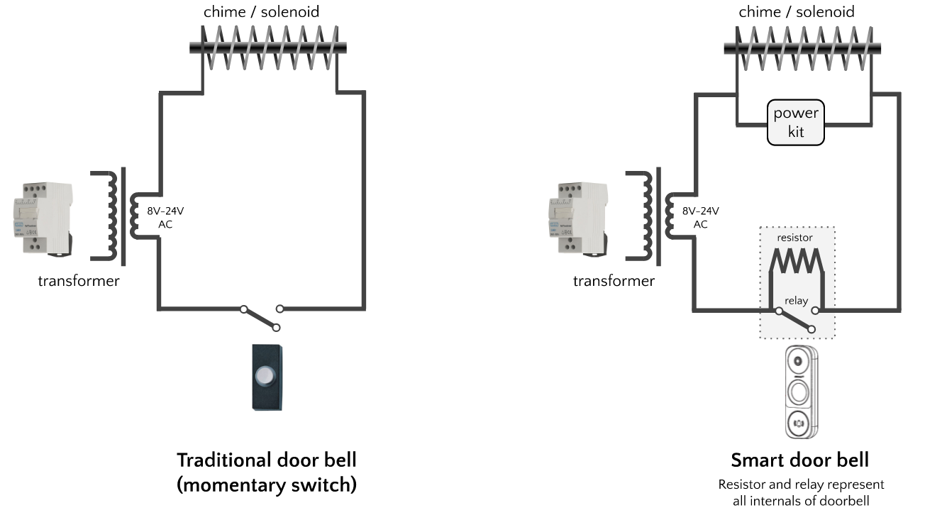
I didn’t have the equipment to directly measure the current used by the DB1 in normal use, but the Google Nest Hello environmental report rates its energy use at 25 kWh / year, which is equivalent to 2.85W. Using I = P÷V (the power formula), at 12V the current would equal 0.2375A, or let’s call it 200mA - 300mA. From my own measurements, the voltage drop across the doorbell when supplied with 12V AC was about 11.6V. Using Ohm’s law, R = V÷I = 11.6V/0.2375A = 49Ω. When the doorbell is pressed, its resistance drops to near-zero and so does the voltage drop I measure across it. I therefore think it’s reasonable to visualize these doorbells as a resistor and a relay in parallel.
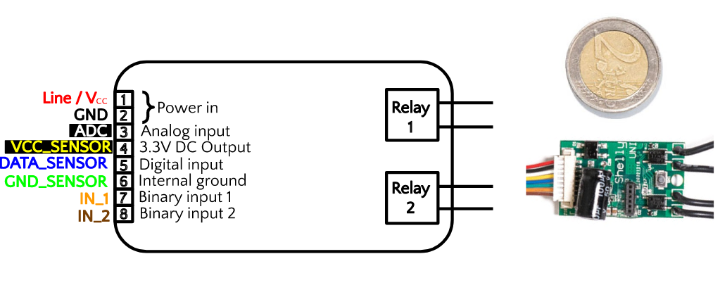
I decided to find a different route. Unlike other Shelly devices, the €11 Shelly Uni can be powered by 12-24V AC. Therefore, I could power it from the existing doorbell wiring, without the need for a separate DC power supply or various bridge rectifiers (in fact, it has an onboard bridge rectifier). The Uni is an ESP8266 with two output relays (which I didn’t use) and a selection of useful sensors for detecting binary or analog inputs. My new plan was to power a Uni by connecting it in parallel with the existing doorbell AC power supply, and then to detect button presses by connecting the IN_1 binary input contact to the doorbell circuit.
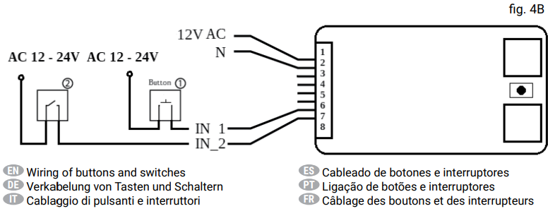
Use of the Shelly Uni to detect dumb doorbell presses is discussed in forums here and here. In these threads, the Shelly is powered by the same source as the doorbell chime transformer, but it is detecting a dumb doorbell (basically a momentary switch), not a smart doorbell. The suggested diagram is very close to one of the configurations documented in the Shelly Uni user manual for AC buttons and switches:
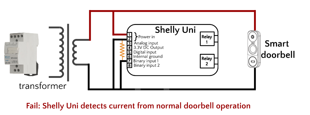
I did my best to turn this diagram and the tips in the above forum posts into an implementation for a smart doorbell, but I didn’t find a way. I tried adding various resistors across the IN_1 and N contacts, and also tried adding the DB1’s supplied power kit.
For the record, my best attempt to wire this up is shown below, with the resistors/power kit represented in orange. In retrospect it is pretty clear that a resistor/power kit connected in this way is pointless, because it is short-circuited. I also see that my attempt to connect the doorbell directly to the Uni’s IN_1 was misguided, because it meant that the Uni’s IN_1 and N were short-circuited and could have not a voltage difference for the Shelly to detect.
To move forward, I decided make life easier by isolating the doorbell circuit from the Shelly Uni by using a relay. This would split the circuit in two: one half would be the doorbell controlling a relay, and the other half would be a Shelly Uni detecting if the relay was on or off.
The doorbell half of the circuit would be wired in the normal way recommended by for any smart doorbell, with the relay standing in the for the chime. Doorbell chimes are basically solenoids, just like relays. When energized, their magnetic field moves a piston hammer (chime) or a contact switch (relay). Since smart doorbells are designed to work with solenoids, I figured the first part of this puzzle would basically involve putting a relay in place of the chime in the regular installation diagram. I bought a 24V AC coil non-latching single pole relay from Radionics for about €7 (if I had more patience I could have got one for half that price on ebay).
On my first attempt I left the power kit out of the circuit, and found that this caused the relay to be unstable. The relay might close spontaneously, or would not open after the doorbell button was released. There was too much current going through the relay coil from the normal operation of the doorbell. With the power kit connected in parallel across the relay, the instability disappeared.
I initially understood the power kit as a resistor that allowed some current to bypass a solenoid, but it is more complicated than that. User @fredkruger from the IPCamTalk forums opened up his power kit and posted a photo:
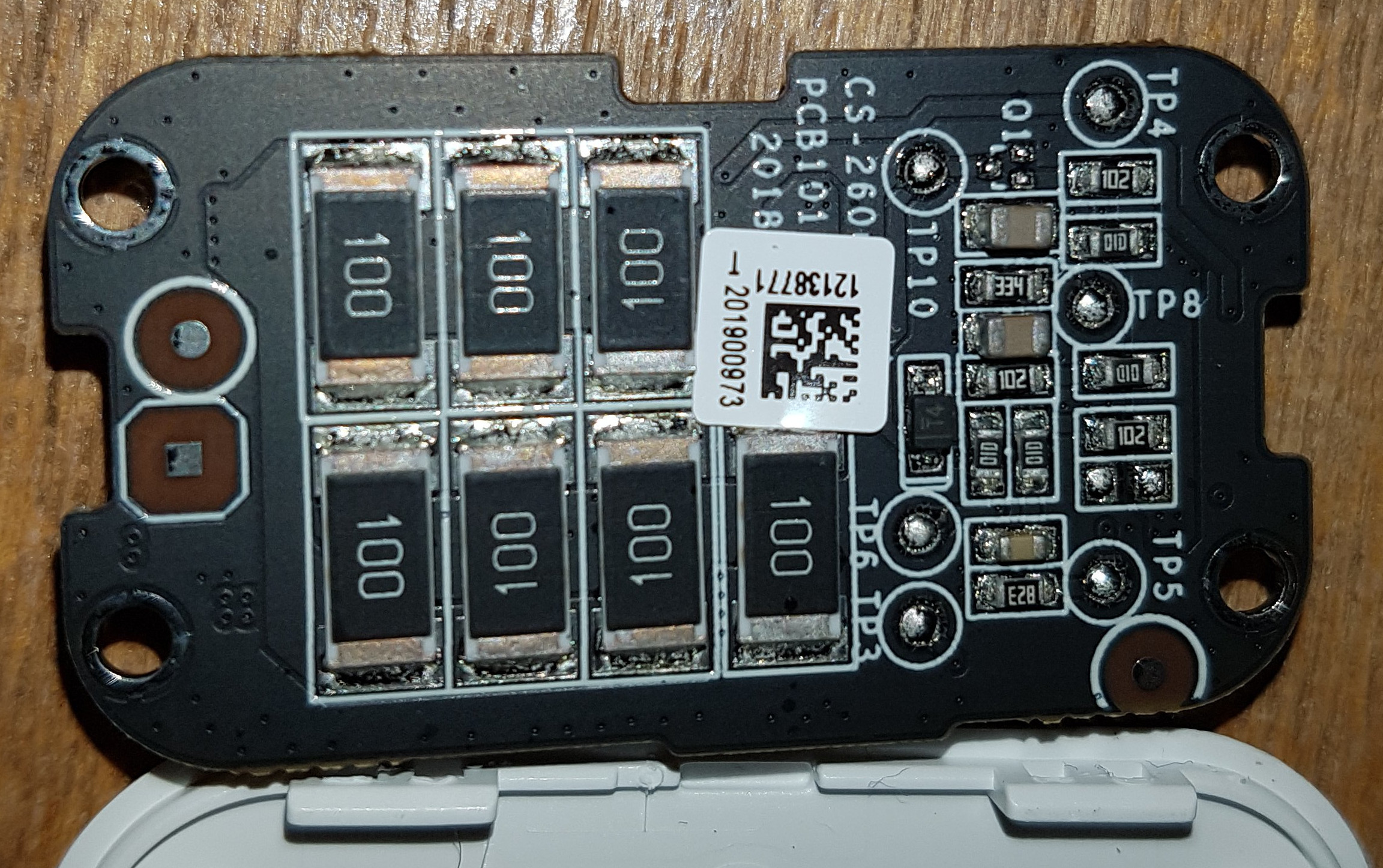
My hypothesis is that the power kit understands the power consumption of the smart doorbell, and allows that current to pass through it with near zero resistance under normal conditions, effectively bypassing any solenoid that it is parallel with. I think that it detects the voltage change in the circuit when the doorbell is pressed, and switches to preventing that current flowing through it, effectively diverting it to the solenoid. I haven’t tested this hypothesis, but I’d be fascinated to hear other people’s opinions on it.
With the power kit installed, the DB1 could control the relay exactly as I hoped, as shown in this slow-motion video of a button press. You can see the relay closing at the same time that the multimeter measures a drop in voltage across the doorbell as the doorbell closes the circuit (note: I was powering the doorbell with 24V AC during this test).
In the other half of the circuit, I would detect whether the relay was open or closed by connecting the Shelly Uni’s IN_1 contact to one of the relay’s output contacts. The Shelly Uni user manual provides a diagram for detecting AC voltage through a momentary or toggle switch (shown previously), which are electrically equivalent to a relay. Consequently I initially supplied the relay’s output contacts with 24V AC. At first it seemed that this worked, but after a day of operation I could see it was clearly unstable. The Shelly would not consistently detect doorbell presses, and it would also only detect when the doorbell press ended, not when it started. It turned out I wasn’t the first person to notice these problems.
I found this Shelly forum thread (in German, Google translate version here) in which users @thgoebel and @DIYROLLY discuss the same frustrations of detecting AC with the Shelly Uni, and conclude that it either has a design flaw or that the user manual incorrectly describes it supports detecting AC at its inputs. User @thgoebel makes the practical suggestion to just switch to DC if possible, or if not possible to add a diode to half-rectify the AC signal into the input sensor.
Final Circuit Diagram
I decided that it was easier, and probably more reliable, to switch to DC. This basically involved removing AC from the relay’s output contacts and replacing it with a 1.5V battery. Then I had to figure out where to connect the other other side of the battery. The Shelly manual is silent on this question, but I decided to try connecting it to the “Internal Ground” sensor, which is shown as unused in the relevant diagrams from Shelly. Finally, it worked.
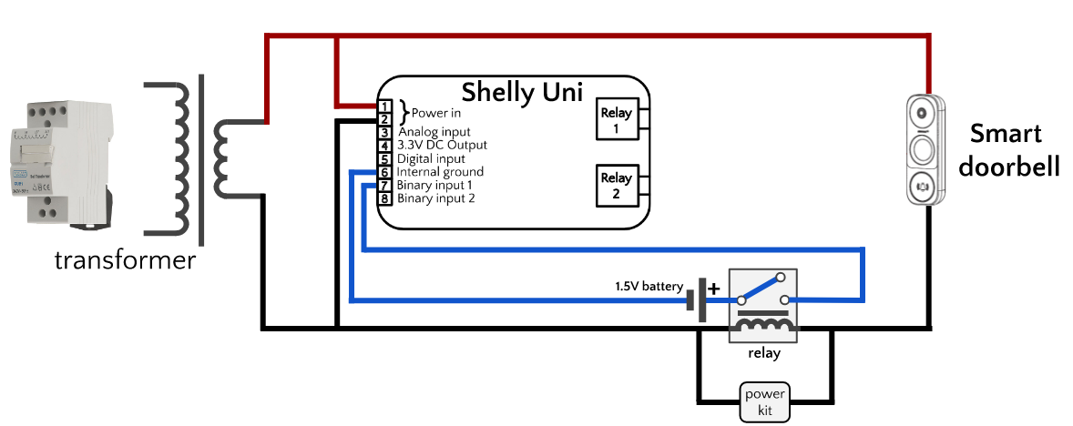
The battery in this circuit should last nearly forever. It is only consumed when the doorbell is pressed. In the Shelly forum thread linked previously, user @thgoebel reported that the Shelly Uni input sensor consumes about 1mA of current. Assuming 2 seconds per doorbell press and 5 visitors per day gives about 1 hour per year of battery consumption. Therefore, yearly energy consumption is about 1mAh. A cheap AAA battery has a capacity of about 850-1200mAh, and would therefore last about a thousand years! (unfortunately, its shelf-life is probably only 10 years 😖)
Assembly
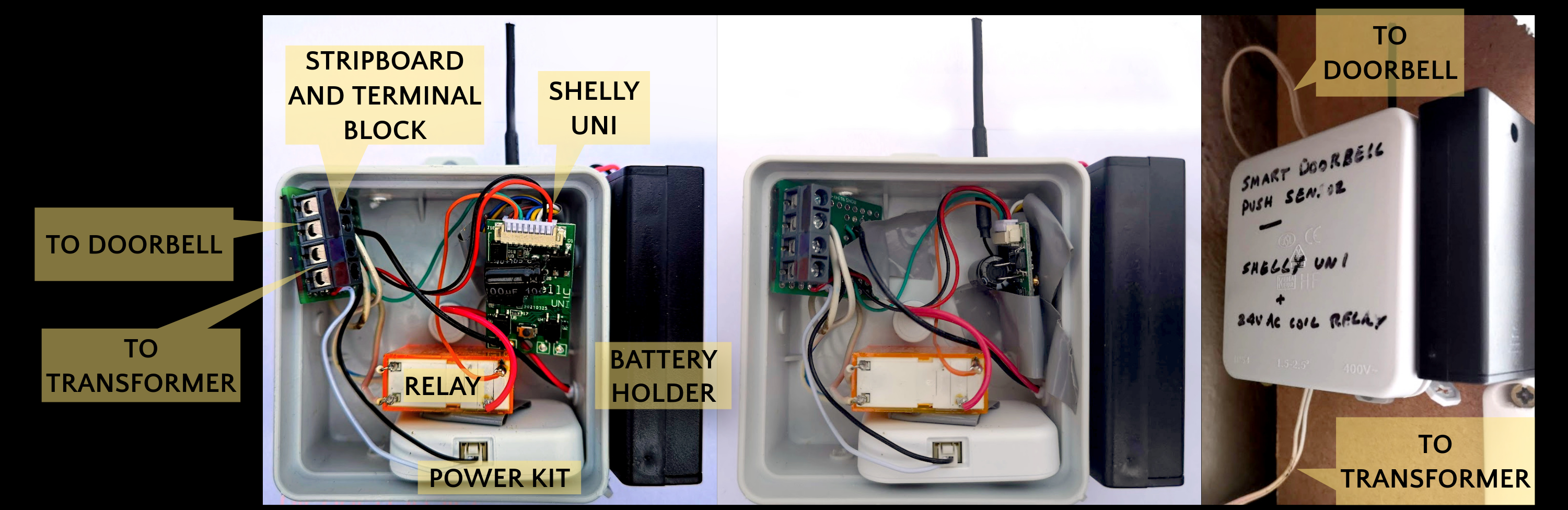
After getting a prototype working on the dining room table with sticky tape and lever wire connectors, I started final assembly. I used a small piece of stripboard to solder the circuit together, with a terminal block to receive the external wiring to the transformer and doorbell. I packed the pieces into a small enclosure as shown, with the Shelly Uni WiFi antenna poking out the top. Finally, I mounted it on the inside of my electrical consumer unit cabinet.
Cost of components
The total cost of the project (excluding time of course!) came to about €23 Euro, with most of the pieces bought from Radionics, whose Irish outlet happens to be located a short walk from my home. The components could probably be ordered on AliExpress or Ebay for a fraction of that price.
| Item | Price | Details |
|---|---|---|
| Shelly Uni | €10.90 | Shelly |
| Relay module (24V AC Coil Non-Latching SPDT) | €7.15 | RS Online |
| Battery holder | €0.74 | RS Online |
| Strip board | €2.26 | RS Online |
| Terminal block | €0.87 | RS Online |
| Junction box | €1.06 | Example item from Irish electrical retailer |
| TOTAL: | €22.98 |
Notes on voltage
Once everything was working smoothly, I experimented with voltage. I had done most of my testing on 24V AC, but found that I could switch the transformer over to 12V AC and everything continued to work fine. I have left it at 12V ever since.
Notes on mechanical vs electronic chime
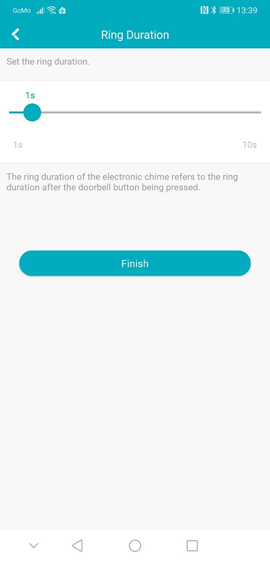
In the doorbell app settings you have various options relating to how the doorbell should try to sound a chime. You must set this to either “mechanical” or to “electronic”. Mechanical will momentarily switch the Shelly’s input. By selecting “elecronic chime” you can adjust the duration up to 10 seconds. For example, if you set it to 5 seconds, the Shelly input sensor will switch on for exactly 5 seconds, starting when the doorbell button is pressed.
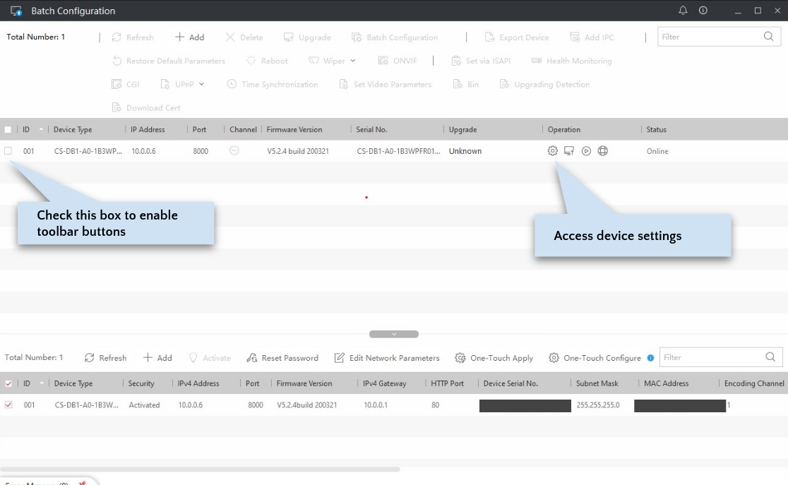
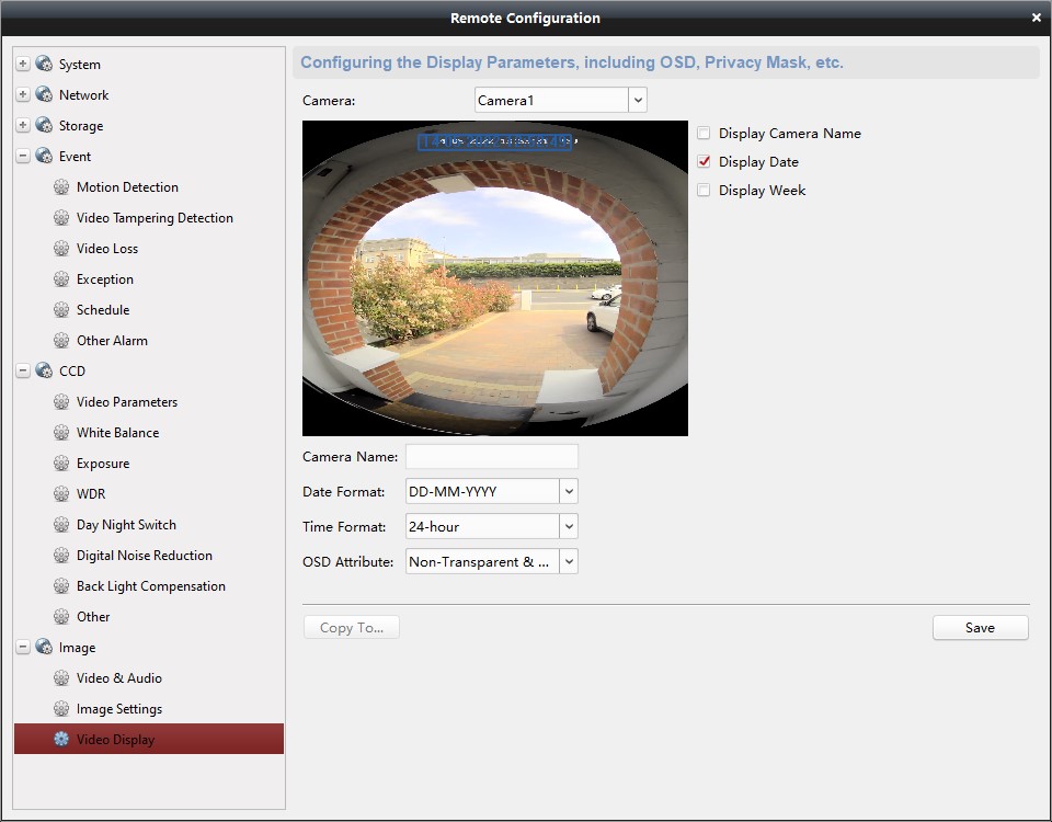
The Desktop Configuration Tool
Although some configuration options are available via mobile apps, advanced configuration is possible by using a desktop app. The “Configuring Doorbell Tips” section of the HikVision Doorbell 101 contains links to the desktop applications you can try, all of which seem to be repackaged versions of the base “iVMS 4200” application, give or take some features. I tried iVMS-4200, EZVIZ PC Studio and HikVision’s Batch Configuration Tool. The Batch Configuration Tool seemed to be the most complete, stable, smallest and fastest, and is the one I settled on. I read on the IPCamTalk forums that later versions of the Batch Configuration Tool had removed some options and that the preferred version is v3.0.2.6. David L provides links to that version on IPCamTalk, and here it is on the Nelly Security website (and here it is on Archive.org in case the previous links stop working).
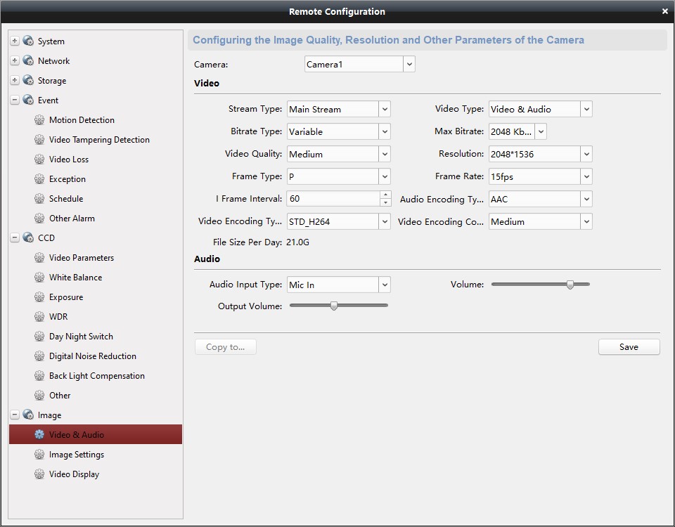
Some things you might want to do with the Batch Configuration tool:
- Increase the framerate from the default
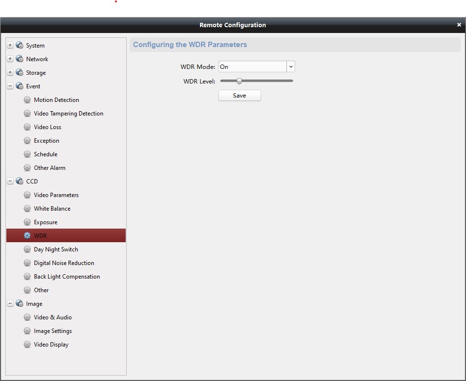
- Play with colour profile, white balance and so on to suit the doorbell’s location
- Flash the doorbell firmware (e.g., to a version that supports ONVIF or removes the ugly “EZVIZ” logo)
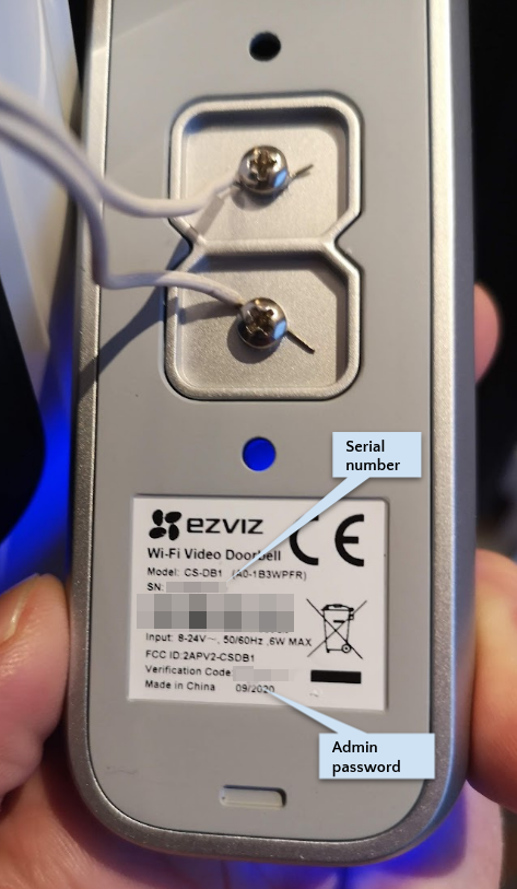
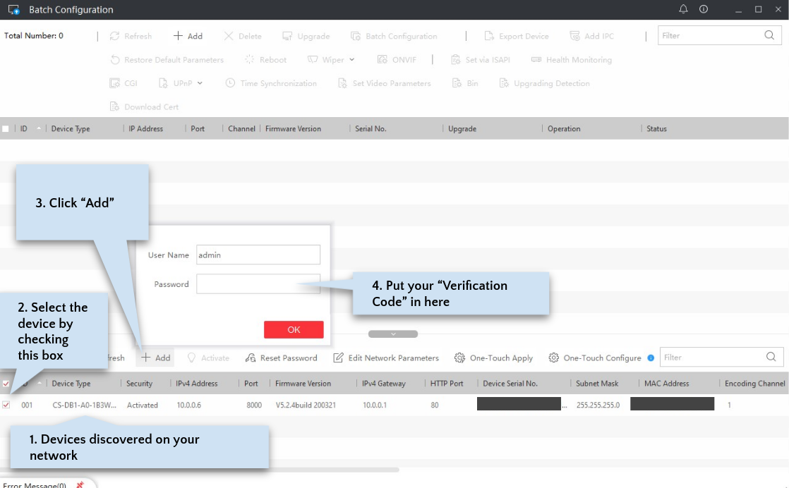
The desktop applications will not win any awards for usability, but they work (mostly). To configure the device you will need to get your admin password, which is the “Verification Code” printed on the label on the back of the device. I recommend you take a picture of the whole label.
WARNING: Some words of caution worth repeating from the 101: Do not change the admin password, even if prompted!
DO NOT change the admin Password in iVMS-4200 or Batch Config. Tool. We found when loading the Batch Configuration Tool for the first time and your Doorbell is Discovered, it will show as “not activated” under security (IGNORE THIS), DO NOT Click the Activate Button. It will force you to set a NEW admin Password on your device (Doorbell) which for most Hikvision Cameras would be a normal process but in this case it disrupts future re-inclusions/configuration through the Mobile Apps. Once done, it is not reversible and cannot be Reset either by Factory Settings Reset or Firmware Reload.
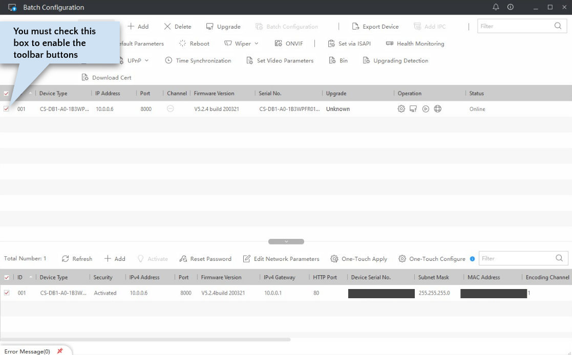
The app contains two main areas. The bottom area lists devices discovered on your network. After you “add” these, they appear in the top area, where you can perform actions on them. Note that for a device to be “discovered”, you need to be on the same network as the device. This means you must have already configured the doorbell using one of the mobile apps, or have connected your PC to the doorbell’s own Wifi access point, which is available to connect to when you first power on the doorbell or do a full reset. If you are on a different network than your device, but it is still routable (e.g., you can ping it), then you can use the “+Add” button in the toolbar to directly add it by IP address to the top area.
Changing the Firmware
The HikVision Doorbell 101 contains a list of firmwares that are compatable with these devices. Different firmwares support different features, e.g., ONVIF, Google Assistant/Alexa and configurable motion detection zones. I had no interest in Google Assistant or Alexa support, given that the point of buying this doorbell was to try to get way from those companies. However, ONVIF and motion detection were important to me, so I chose the HikVision firmware version “200321” (there is a more recent HikVision firmware version 211101, but I have avoided it because a user on the IPCamTalk forum reported that it removes the camera snapshot URL feature).
Many of the download links given in the 101 for various firmware brands (including the HikVision ones) seem to be restricted to North American IP addresses. To download them from Europe or elsewhere, you might need a VPN, to download them from a VPS server, or to get a friend in North America to email them to you.
To update the firmware, I followed the instructions given by @alexdelprete on the IPCamTalk forums. Here are those instructions with accompanying screenshots.
WARNING: If you choose to update your firmware, you do so at your own risk. Some people have bricked their devices. You can read the HikVision Doorbell 101 to understand those risks.
First, use the official Android/iOS app that corresponds to the current firmware on the doorbell (e.g., EZVIZ) to upgrade to the latest firmware version available.
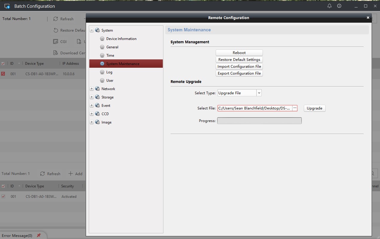 Use Batch Config v3.0.2.6 (not the latest one) to upgrade Firmware (SYSTEM->SYSTEM MAINTENANCE->Remote Upgrade)
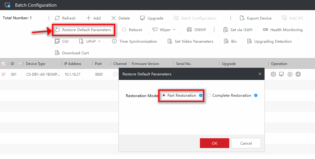 Use Batch Config v3.0.2.6 (from main screen) to “Restore Default Parameters”, i.e., reset the config of the device
The doorbell should reboot automatically.
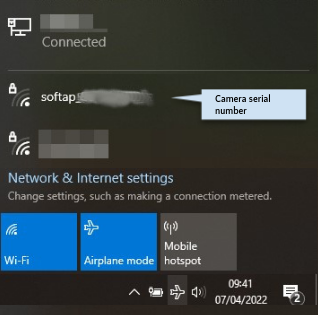
Using the PC (that you have installed Batch Config Tool on), connect to the WiFi access point of the doorbell (with an SSID like “softap_<serial_number>”). The wifi password is “softap_<verification code>” (where the serial number and verification code are found on the label on the back of the device).
NB: If you ever mess up and need to reset your doorbell (by pressing the button inside the case for 5 seconds), you can start over at this point. After reset, the doorbell will be advertising an
softap_SSID as shown here. I once needed to start over at this point after changing the doorbell WiFi to one that didn’t exist. Oops.
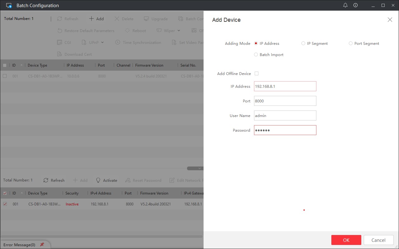 In Batch Config Tool the device is listed as a newly discovered device, because you are now connected to the doorbell’s own WiFi network (note the new IP address). Provide the username “admin” and use the “Verification Code” from the back of the doorbell as the password.
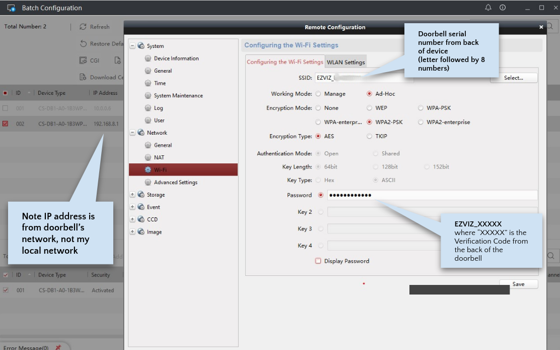 Use Batch Config v3.0.2.6 to change default SSID from “softap_<serial_number>” to “EZVIZ_<serial_number>” and the password to “EZVIZ_<verification code>” (note the uppercase). These values are expected by the mobile apps.
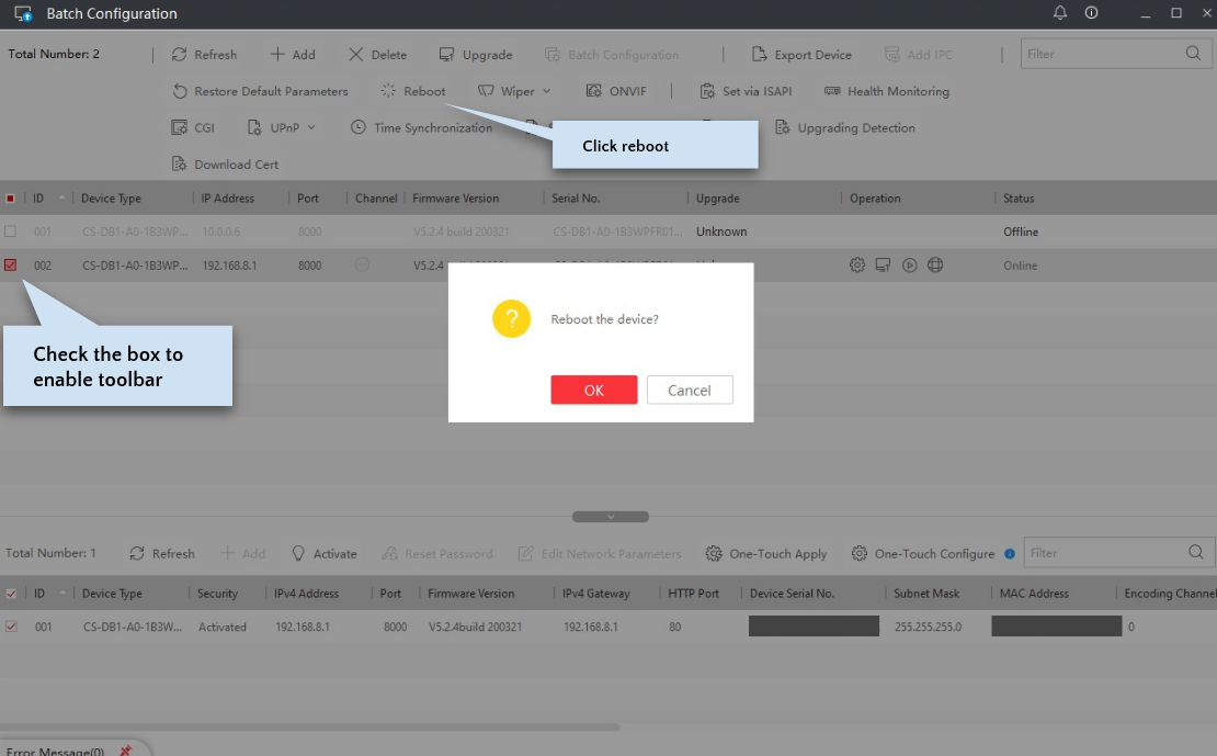 Reboot the device.
Check the list of available WiFi access points on your PC. If you see the “softap_<serial_number>” SSID, it means you didn’t change the SSID, so go back to that step. If you see the “EZVIZ_<serial_number>” SSID then you have succeeded.
Start the mobile app you have chosen (e.g., Hik-Connect, RCA Security, EZVIZ, LaView ONE, Guarding Vision) and configure it like a brand new doorbell.
Enabling ONVIF Support
After the change to HikVision firmware I tried to enable ONVIF using the toolbar button in the Batch Configuration Tool, but got an error. I asked about this in the forums and learned that this was because ONVIF is enabled by default. It turned out that this was true, and I could access the following the doorbell snapshot URL at http://DOORBELL_IP_ADDRESS/onvif/snapshot.jpg, and could configure ONVIF at port 80 on the doorbell’s IP address, using username admin and password equal to the 6 letter Verification Code.
Choosing a Mobile App
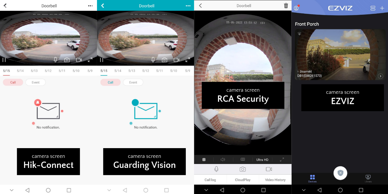
There are a number of different mobile apps that can be used with the doorbell, corresponding to the various brands that have rebadged it: Hik-Connect (for HikVision), RCA Security (for RCA), EZVIZ, LaView One (for LaView) and Guarding Vision (for Nelly). Here are my conclusions having tested them all on Android (I did not test on iOS).
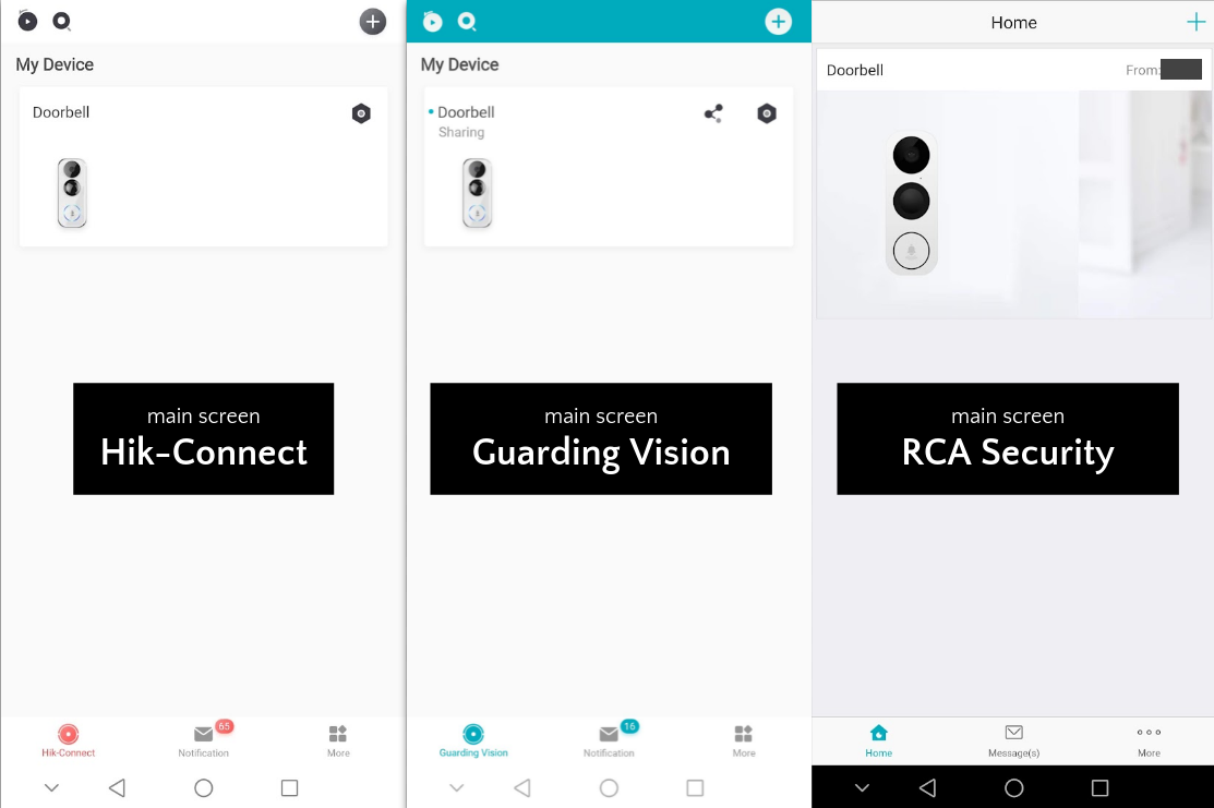
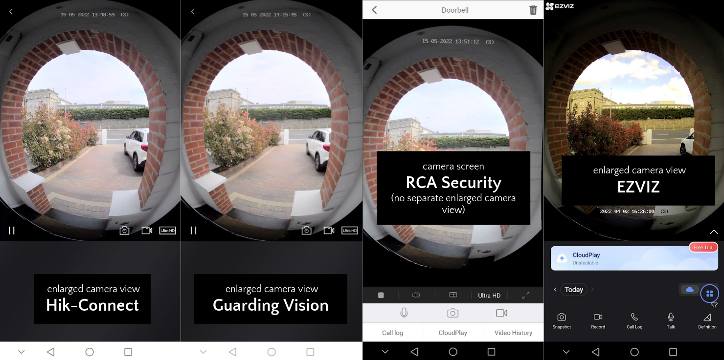
These apps are very similar, and some of them seem to even share the same account backend. So far as I can tell, Hik-Connect and Guarding Vision have an identical user interface, but unfortunately they squash the camera image, which has a high vertical field of view and a natural portrait orientation, into a landscape orientation on the most commonly used screen. The RCA Security, LaView and EZVIZ apps are different and do a better job displaying the camera stream. Unfortunately the EZVIZ app has a prominent ad for cloud storage plastered on nearly every screen, which you can’t get rid of, and which I couldn’t bear to look at. The RCA Security app probably has the best user interface, with touch support for zooming and panning the camera.
With the sole exception of Guarding Vision, I had difficulty using the apps to receive a call on a phone when someone presses the doorbell. In fact, I’ve had 0% success with the RCA Security app, and suspect it doesn’t even support this. As for the other apps, it worked less than half the time on my Huawei P20 Pro, and only about 80% of the time on my wife’s Google Pixel phone (even after enabling all permissions and disabling battery optimization, and so on). The folks at IPCamTalk discussed this and found the Guarding Vision app the be one that works reliably (corroborated by reviews on the Nelly Security site).
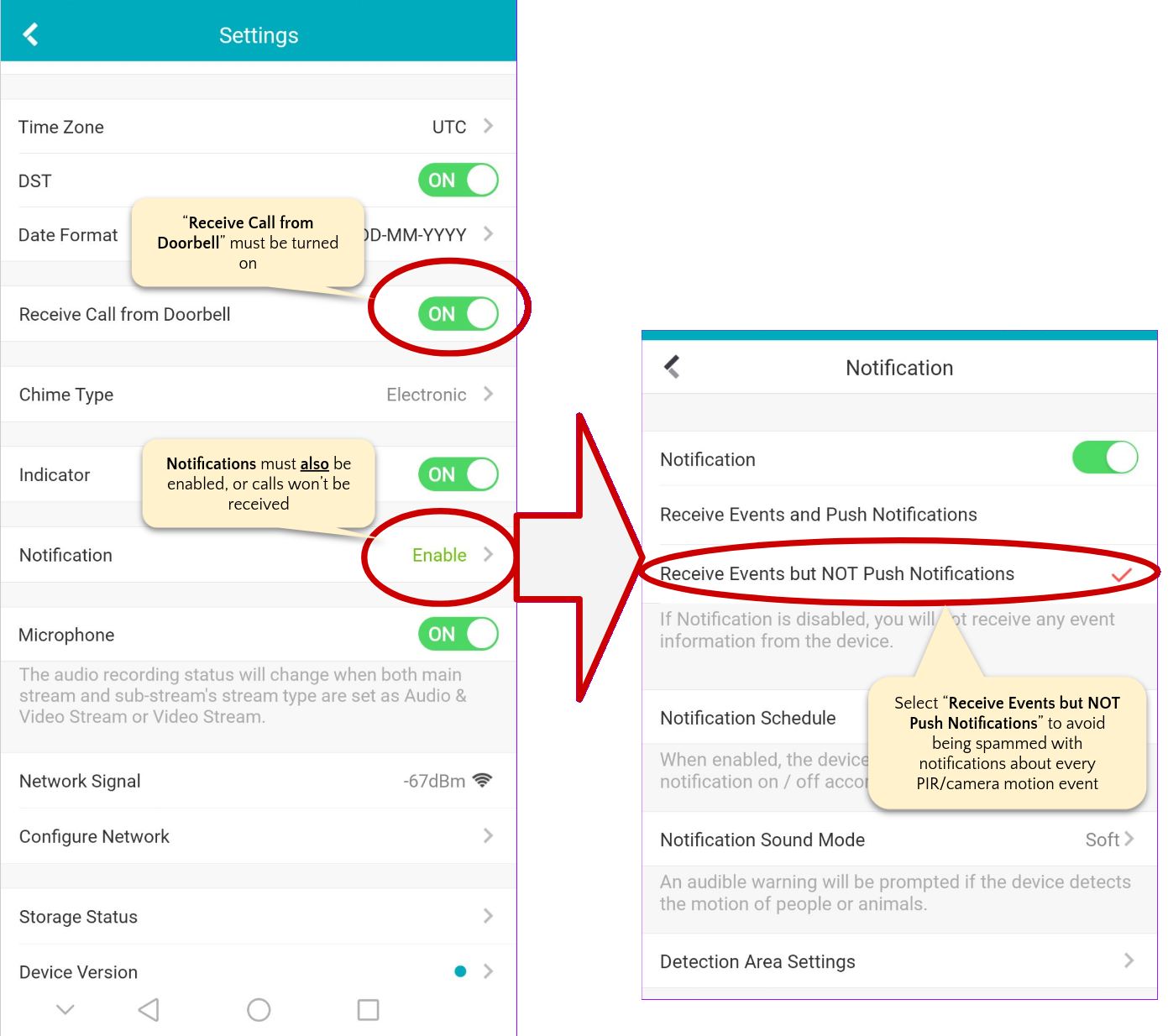
Recommendation: The Guarding Vision app is the most reliable for receiving VoIP calls from your doorbell (we haven’t missed a caller since we started using it).
To ensure that you receive calls using the Guarding Vision app, you need to have your notifications set up correctly. It’s a little unintuitive, but you must have both “Receive Call from Doorbell” and “Notifications” turned on.
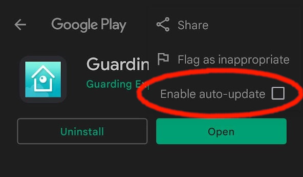
Having finally found a member of this family of related apps that actually works reliably, I was quick to turn off auto-updates for it in the Play Store, in case a future update might break it. I also used the following commands to grab backups of the associated APK files off my phone, so I could reinstall them if something happens to the app and I need to install them on a new device (commands below are in a Linux Bash terminal with ADB installed and USB debugging enabled on the phone, which is connected by USB).
adb shell pm list packages  | grep guardingvision
# output:
# package:com.mcu.guardingvision

adb shell pm path com.mcu.guardingvision
# output:
# package:/data/app/com.mcu.guardingvision-Ja3SvgDCwBbct480CcVoIw==/base.apk
# package:/data/app/com.mcu.guardingvision-Ja3SvgDCwBbct480CcVoIw==/split_config.arm64_v8a.apk
# package:/data/app/com.mcu.guardingvision-Ja3SvgDCwBbct480CcVoIw==/split_config.en.apk
# package:/data/app/com.mcu.guardingvision-Ja3SvgDCwBbct480CcVoIw==/split_config.xxhdpi.apk

$ adb pull /data/app/com.mcu.guardingvision-Ja3SvgDCwBbct480CcVoIw==/base.apk
$ adb pull /data/app/com.mcu.guardingvision-Ja3SvgDCwBbct480CcVoIw==/split_config.arm64_v8a.apk
# etc
Recommendation: Obtain backup copies of the versions of the APKs that work for you, in case they disappear from the Play Store.
Here are some comparison screenshots between the various apps.
It’s worth mentioning that the call quality in all these apps far surpassed my experience with Ring Pro or the Nest Wired doorbells. Video quality was excellent, and sound clarity was good at both the doorbell and the phone, with very low lag (about half a second). It was actually possible to have a conversation, which I never found possible with the rival Amazon and Google products.
Using multiple apps
While testing the various apps I found that I could re-use an account I made on the Hik-Connect app in the RCA Security app, and vice versa. In addition, when I added my doorbell to the Hik-Connect app it appeared in the RCA Security app. It appears that both the Hik-Connect app and the RCA Security apps are frontends to the same backend database where account details and registered devices are stored.
Meanwhile, the Hik-Connect app and the Guarding Vision app are visually identical and clearly based on the same code, but do not share the same backend database. However, I noticed that I could share the doorbell from my Guarding Vision account with my Hik-Connect / RCA Security account. There’s no benefit in having both the Guarding Vision and Hik-Connect apps installed (they have identical UIs), however the RCA Security app provides a much nicer UI for interacting with the doorbell as a camera and two-way intercom. The Guarding Vision and RCA Security apps therefore complement each other well:
| Good Camera UI | Receive VoIP calls | |
|---|---|---|
| Guarding Vision | No | Yes |
| RCA Security | Yes | No |
Recommendation: Install both apps. Use the Guarding Vision app as your master account for managing the doorbell and reliably receiving calls from it. Share the device with the RCA Security app, and use it as your main UI for checking out the camera or initiating conversations over it as an intercom.
How to share a device between Guarding Vision and RCA Security.
I initially had difficulty sharing the doorbell between these two apps, but found one path that worked. Basically, you must first share the device from Guarding Vision to Hik-Connect. As soon as it is shared with Hik-Connect it will appear in RCA Security too. To perform the share, start in Guarding Vision, click the sharing icon on the device, “Share with User”, then “Share via QR Code”. Take a screenshot of that QR code and put it somewhere you can scan with your phone camera (e.g., send to another phone, desktop or printer). Then from the Hik-Connect app, choose “Add Device”, and scan the QR code. This will apply for sharing, and will send a notification to Guarding Vision. As soon as you approve that notification, you should have access to the doorbell from both apps (and you can uninstall Hik-Connect at this point if you like).
Integrating with Home Assistant
After the work above, and with the doorbell flashed with the HikVision firmware, there were three ways to integrate the doorbell into Home Assistant: RTSP, ONVIF and via the Shelly Uni push sensor.
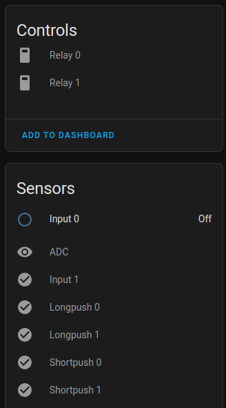
Shelly Uni Push Sensor
You can add the Shelly Uni to Home Assistant either via MQTT or via the Shelly integration. If you are using the Shelly integration, make sure to enable CoIoT on the Shelly as described in the integration documentation. This will ensure that Home Assistant is notified instantly when the doorbell is pressed. When added via the MQTT integration, an Input 0 binary sensor was created that represented the state of the IN_1 binary input contact on the Shelly board. I disabled all the other entities, which corresponded to contacts that were not physically connected to anything.
RTSP
The doorbell provides a hi-def main stream and a low-res sub stream. Only three streaming clients can be active at any one time. The stream URLs are as follows (replace VERIFICATION_CODE AND DOORBELL_IP_ADDRESS with your own values):
- Sub stream:
rtsp://admin:VERIFICATION_CODE@DOORBELL_IP_ADDRESS:554/Streaming/Channels/102/ - Main stream:
rtsp://admin:VERIFICATION_CODE@DOORBELL_IP_ADDRESS:554/Streaming/Channels/101/
It is possible to quickly test the URLs in VLC using Media > Open Network Stream.
You can also create a “XSPF” file on your desktop to act as a VLC shortcut for quickly opening the doorbell stream from your workstation. Create a file named “doorbell.xspf” with the contents below (VERIFICATION_CODE AND DOORBELL_IP_ADDRESS with your own values).
<?xml version="1.0" encoding="UTF-8"?>
<playlist xmlns="http://xspf.org/ns/0/" xmlns:vlc="http://www.videolan.org/vlc/playlist/ns/0/" version="1">
    <title>Doorbell</title>
    <trackList>
        <track>
            <location>rtsp://admin:VERIFICATION_CODE@DOORBELL_IP_ADDRESS:554/Streaming/Channels/101/</location>
            <extension application="http://www.videolan.org/vlc/playlist/0">
                <vlc:id>0</vlc:id>
                <vlc:option>network-caching=1000</vlc:option>
            </extension>
        </track>
    </trackList>
    <extension application="http://www.videolan.org/vlc/playlist/0">
        <vlc:item tid="0"/>
    </extension>
</playlist>
You should be able to doubleclick this file to open the stream directly in VLC.
ONVIF Support
The doorbell can be added to Home Assistant via the ONVIF integration (Settings > Devices & Services > Integrations > Add Integration > ONVIF). Home Assistant will probably auto discover the doorbell. If you need to manually configure it, ONVIF is available at port 80, with the username admin and password equal to the 6 letter Verification Code (from the back label of the doorbell).
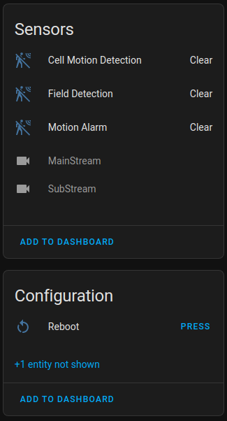
A few different entities will be available over ONVIF:
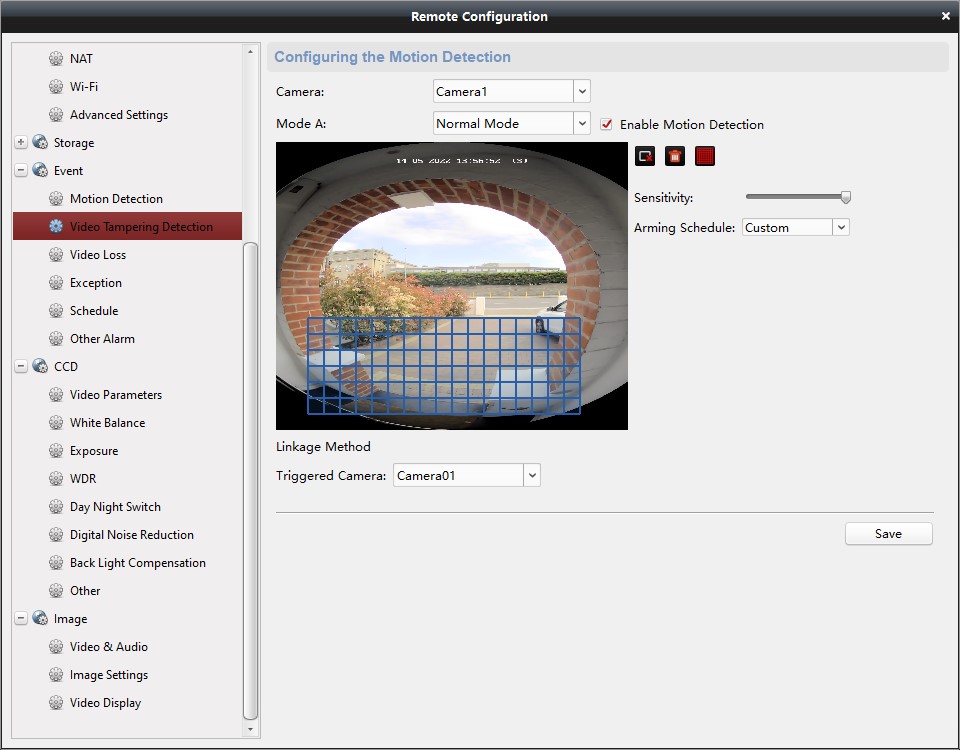
- Cell Motion Detection. I believe this is video motion detected by the doorbell in the motion detection zone that you may have set up from the desktop configuration tool (screenshots in the Desktop Configuration Tool section above)
- Motion Alarm. I believe this is the PIR sensor.
- Field Detection. I don’t know what this is. It has never detected anything for me.
- MainStream and SubStream. Camera entities for the low/high resolution stream. I recommend disabling these entities to help you avoid accidentally using them somewhere and consuming precious streaming connections.
- Reboot. A button that reboots the doorbell.
A doorbell snapshot image is available at the URL http://DOORBELL_IP_ADDRESS/onvif/snapshot.jpg, if you want to include it in mobile notifications etc.
Maximum Stream Limitation
The doorbell supports a maximum of three simultaneous video streaming clients. To avoid getting errors on your phone when you try to answer the door, you need to be careful not to use up all the streams in Home Assistant. I suggest that you disable the camera entities that the ONVIF integation provides, and that you don’t add a Generic Camera integration for the direct RTSP stream. Instead, set up a proxy that will forward a single stream from the camera to as many clients as you like.
If you are using Frigate (which I highly recommend) you can enable the “RTMP” role for the camera. Frigate will then proxy the doorbell stream (which it would have been receiving anyway) to a new camera entity that the “Frigate NVR” integration will create for you. When you stream that camera entity, you are streaming from the Frigate proxy, not directly from the doorbell.
If you do not intend on using Frigate, I suggest you consider installing the RTS2P addon (Settings > Add-ons > Add-on Store > overflow menu > Repositories > Add, paste in https://github.com/snowzach/hassio-addons, click “ADD”, and then select and install “RTS2P”). RTS2P runs the Live555 library to proxy RTSP streams. You can configure it with the RTSP stream to your doorbell, and then add a “Generic Camera” integration that points to the proxied RTSP stream.
In my installation I use Frigate, which uses up one RTSP stream. My TV popup (see below) uses up one more stream, but only if the TV is in the “playing” state. That leaves one or two RTSP streams (depending on the TV) left over for answering the door via the mobile app.
Frigate Integration
The doorbell RTSP stream works with Frigate without any special FFMPEG magic. Frigate-Hass-Card provides an excellent UI for viewing the doorbell from within HomeAssistant, allowing you to quickly view the doorbell stream and quickly navigate between and replay recent events.
Unfortunately, there is no way to do two-way communication with the doorbell from Home Assistant. That requires one of the apps, and the peer-to-peer connectivity they implement.
TV popups and other automations
Some of the doorbell automations I’ve implemented so far are:
- TV popup. The RTSP stream from the doorbell works well with the WebRTC Camera integration. This means it can be displayed on an Android TV Picture-in-Picture popup, as described in a previous post.
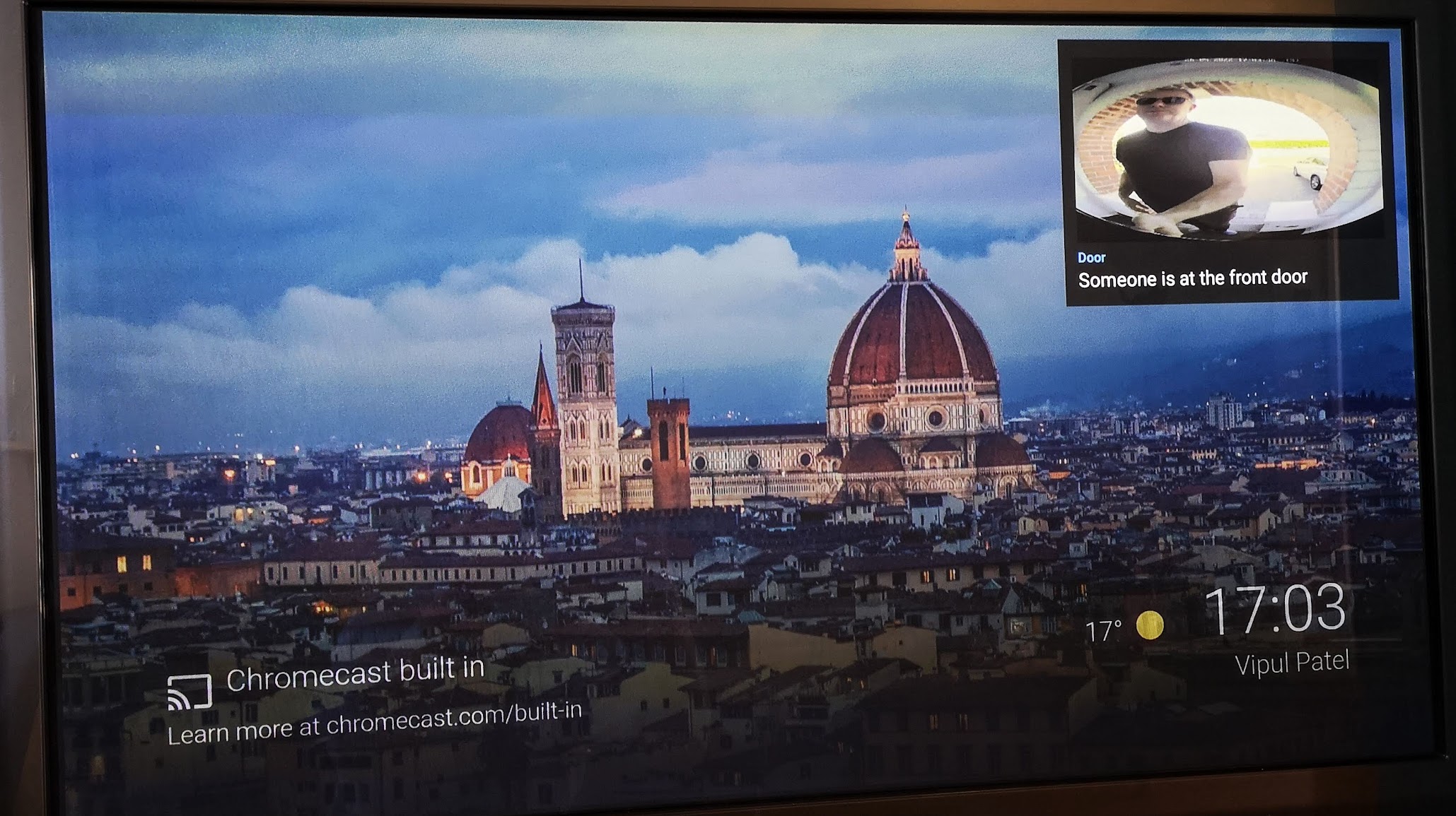
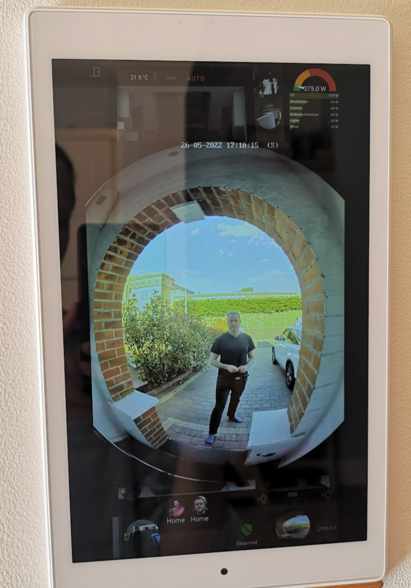
- Wall tablet popup. I have also created an automation to use browser_mod to display the doorbell camera in a popup on my kitchen wall tablet whenever there is human motion detected in the driveway.
- Visitor announcement. I don’t have a physical doorbell chime, so I play a “ding-dong” and a spoken message on Sonos speakers whenever the doorbell is pressed.
Security Analysis
I found myself more concerned about the security of this device than I was for its predecessors - a Google Nest doorbell and an Amazon Ring Pro. On reflection, I think I was spooked by HikVision being a Chinese state-owned company, but there is really no reason I should trust Google and Amazon products any more than this one. In any case, I decided while writing this post to take a close look at who this device tries to talk to.
Related work:
@msmcknight on the IPCamTalk forums provides a good analysis of the device’s traffic. First, he makes some valid complaints about the permission-creep of the app, which requires access to location, camera, microphone and storage. I confirmed this in the Guarding Vision app, although I also noted that I could disable location and camera permission after setup without any consequences. I could also disable storage permission, but the app started nagging for storage access every time I open it.
Recommendation: once your app is set up, revoke location and camera permission.
He also identified the following traffic from his firewall:
- time.ys7.com:123 (NTP). First hitting a server in China (time.ys7.com)
- 0.amazon.pool.ntp.org:123 (NTP). After configuration NTP via the Desktop Batch Config Tool.
- ICMP - pings the router/gateway every 30 seconds.
- Destination port 8800. Amazon hosted server (also accessed by app)
- Destination port 8666. Amazon hosted server (also accessed by app)
- Destination port 6500. Amazon hosted server (also accessed by app)
- Destination port 31006. Amazon hosted server.
- Destination port 6002. An unresolvable server in Singapore.
- Destination port 5228. Google hosted server.
He found that he could continue blocking destination ports 6002, 5228 and 6500 without damaging functionality.
A related piece of research is presented in this video from Sharkfest21 (the conference for the Wireshark network protocol analyser) in which Simone Mainardi describes how he analysed traffic from IOT devices in a project that was jointly supported by the European Union NGI and Horizon 2020 research funds. His materials are online at this dropbox link. He monitored the devices using a man-in-the-middle testbed, based on a Raspberry Pi running a bridged WiFi access point (using hostapd), and he monitored passing traffic using tcpdump. He did not specifically test the EZVIZ DB1 doorbell, but found some interesting traffic patterns on related camera products from EZVIZ:
- Multicast LAN traffic using the Simple Service Discovery Protocol (SSDP) protocol that discovered other services on the LAN (in his case, a D-Link camera responded).
- NTP traffic
- 3 Amazon EC2 hosts in the EU-West region (Ireland)
- 2 Tencent cloud hosts in Singapore. The traffic to one of these consisted of UDP packets discovering the WAN IP address of the doorbell.
- Video streams resulted in a MQTT message from Amazon EC2 followed by a TCP stream containing video data.
- A HTTP connection to Amazon AWS that uploads data in cleartext HTTP, with a hostname of “backupserver”.
Later in this analysis I’ll show how I observed similar traffic from the DB1 doorbell.
The AWS upload is potentially concerning. I examined Simone’s pcap file in Wireshark. Here’s an abridged copy of the HTTP request from his EZVIZ camera:
POST /sdk.post HTTP/1.1
Accept: *.*
Host: backupserver:8080
Connection: close
Content-Length: 38730
Content-Type: application/x-www-form-urlencoded

filename=undefined&code=
hikencodepicturecb43c845258055c97470644703fb5bfd
<38Kb of data>
The Amazon EC2 server response:
HTTP/1.1 200 OK
Date: Sat, 08 May 2021 13:50:46 GMT
Server: nginx
Content-Length: 54
Connection: Close

/image/pic/fc4b013f86fd428690075c605c53a44f?c=a0d85aaf
It appears that his EZVIZ camera was uploading a picture, probably a snapshot, to Amazon. It is bad that it uses unencrypted HTTP (although the payload image itself is “hikencoded”, whatever that means) and that there is no apparent authentication involved (and therefore it might be possible for the image to be accessed by unauthorized parties). In my analysis below I will show some similar traffic from the DB1 doorbell, which is at least properly encrypted. I’ll show later why I believe these uploads are simply camera snapshots of events, allowing a gallery of events to be displayed in-app.
What I expected to find
I am experienced with low level networking and peer-to-peer systems. As CTO of Demonware I was closely involved in design and implementation of the peer-to-peer code and hosted platform that connect millions of players in real-time in the Call of Duty video game franchise, and many other video games. Based on my recollection of implementing the ICE and the STUN RFCs for establishing peer-to-peer communication through NATs, I expect a product like the DB1 doorbell to generate the following types of traffic at a minimum:
- Normal housekeeping traffic like NTP for time synchronisation, DHCP for obtaining an IP address and DNS server information, DNS queries for various servers, and ICMP (pings).
- TCP traffic to a server that sends events corresponding to doorbell presses and motion detection.
- TCP (possibly HTTP) traffic to a server (possibly the same one above) where it can upload snapshots of events to be displayed in-app.
- UDP traffic to two or three servers on various ports to discover the WAN IP address and test the type of Network Address Translation (NAT) the doorbell is hosted behind. See the STUN RFC for more info about NAT types.
- Regular UDP messages to one of the above servers that act as “heartbeats” to keep a NAT port binding alive at the router’s external/WAN IP address (maybe every 30 seconds - 60 seconds).
- UDP or TCP traffic from a server (probably one of the previous servers) for the purpose of coordinating peer-to-peer connections, along the lines of the STUN and ICE RFCs. This basically tells the doorbell to initiate a connection out to a peer that is seeking to connect (e.g. the Hik-Connect app on your phone).
- UDP traffic to various different IP/port endpoints where the phone app might be reachable. I’d expect my mobile carrier’s IP address range to show up here, and my WAN IP and my phone’s LAN IP.
See this great PDF from the IETF for a primer on punching holes through NATs for peer-to-peer communication using ICE and STUN.
Based on the above list, I’d expect the doorbell’s functionality to make it look quite chatty. This didn’t seem to explain everything @msmcknight reported though, so I decided to do a deeper analysis.
Methodology
I initially used aircrack to put my WiFi interface into “monitor” mode on the same WiFi channel as my router, added my WiFi’s PSK Key in raw hex format into Wireshark (Edit > Preferences > Protocols > IEEE 802.11 > Enable Decryption), started a Wireshark capture in promiscuous mode, and power cycled the doorbell to get it to reconnect to the WiFi. At this point Wireshark would capture its WiFi session key and decrypt its ethernet traffic (and anything else that connected to the WiFi after the capture started).
# see if there are other processes managing network interfaces that might interfere
airmon-ng check
airmon-ng check kill # kill interfering processes
airmon-ng start wlp2s0 4 # Put interface wlp2s0 into monitor mode on channel 4
# Return the WiFi interface to normal
airmon-ng stop wlp2s0mon
This passive monitoring approach was pretty easy to set up but many packets were not captured due to the distance between my workstation and the doorbell. This made it hard to confidently analyse what the doorbell was doing.
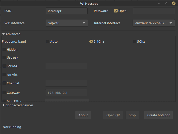
I therefore switched to a Man-in-the-Middle attack. I used Linux WiFi Hotspot to create a new software-based access point running an open WiFi with the SSID “intercept”, which forwarded traffic to my wired ethernet interface. This created a new network interface called ap0 on my machine. In Wireshark I was immediately able to capture all traffic on the “intercept” WiFi using the ap0 interface.
To capture the doorbell traffic, I used the Batch Config Tool to switch its WiFi to the “intercept” network, and I rebooted it.
During testing I tried blocking access from the “intercept” WiFi to various services that the doorbell would try to talk to. I did this with IP tables as follows.
# Back up IPtables
iptables-save > /tmp/iptables.bak

# Turn on logging to see things getting blocked
iptables --insert FORWARD -m limit --limit 5/min -j LOG --log-prefix "dropping: " --log-level 7

# Block port 443 (effective immediately)
iptables --insert FORWARD --in-interface ap0 --protocol tcp --dport 443 -j DROP
# Block destination IP 54.154.13.64 (effective immediately)
iptables --insert FORWARD --in-interface ap0 --protocol tcp --destination 54.154.13.64 -j DROP

# Restore IPtables between tests
iptables-restore < /tmp/iptables.bak
When I was finished testing, I switched the doorbell back to the normal network by connecting the Windows machine with Batch Config Tool to the “intercept” network, and re-adding the doorbell under its “intercept” WiFi IP address. I was then able to reconfigure it to connect back to the normal WiFi, and reboot.
Housekeeping Traffic
At startup, the doorbell exchanges DHCP traffic with the network gateway (router) to obtain an IP address. It then performs some DNS queries to resolve its NTP server and “litedev.ezvizlife.com”. Later, it performs occasional DNS queries to resolve alarm.eu.s3.amazonaws.com (which is a CNAME for Amazon’s Simple Storage Service). It goes on to ping the network gateway every 15 seconds.
LAN Service Discovery Requests
At startup, the doorbell sends various UPnP network discovery requests. Specifically, it sends Simple Service Discovery Protocol (SSDP) “M-SEARCH” requests to the multicast address 239.255.255.250:1900, with the queries device:InternetGatewayDevice, service:WANIPConnection, service:WANPPPConnection and upnp:rootdevice. This is an apparent attempt to discover the WAN IP address over UPnP.
However the last one of these requests seems to be a little overzealous. Section 1.3.3 of the UPnP spec specifies that all UPnP devices should respond to “M-SEARCH” queries for upnp:rootdevice. In my case, all of my Reolink cameras responded to it. The doorbell does not appear to make any use this information, and it doesn’t complain if it doesn’t get any responses. I assume this SSDP query is a vestige of some previous device this firmware was used on.
Recommendation: For peace of mind, isolate the doorbell onto a separate network from cameras and UPnP devices in your home that it might access via multicast, and which might contain sensitive information. E.g., don’t allow it to discover your NAS or baby monitor.
Local API traffic
RTSP traffic is served from port udp/554. The ONVIF API is served from port tcp/80. The management interface that the desktop Batch Config Tool connects to is served over tcp/8000.
Ongoing Device Traffic
The doorbell talks to a lot of IP addresses, which seem to be randomly selected from a large pool of candidates at startup. Across 4 test runs (with the doorbell rebooted between each test), I captured traffic to 27 different remote IP addresses at 33 different IP:port endpoints (i.e., some IP addresses host services at multiple ports). Nearly all the endpoints were different in each test run. In fact, the only IP addresses seen in multiple test runs were the ones that litedev.ezvizlife.com resolves to. The IP addresses I observed were all located in either Amazon’s AWS datacenter in Ireland (“EU-West”), a Tencent datacenter in Germany, or a UCloud datacenter in the United Kingdom. HikVision/EZVIZ seems to have taken care to locate their data processing in the EU, possibly to comply with GDPR privacy regulations (side note: some of those European servers are operated by other Chinese companies, and the UK is no longer in the EU). I am located in Ireland, so it is very possible I am getting servers close to me returned. Users in other continents may see completely different IP addresses.
Excluding litedev.ezvizlife.com, none of the other IP addresses were discovered using DNS. I tried to find where these IP addresses came from by unpacking the firmware using binwalk, and searching the unpacked contents with grep and a hex editor. The only hardcoded IP address I could find was for a DNS server (which I never saw used).
Incidentally, I found DNS entries hardcoded in the firmware for litedev.ezvizlife.com, time.ys7.com, alarm.ezviz7.com, dev.ezviz7.com and devlog.ys7.com. litedev.ezvizlife.com is the main DNS entry used by the doorbell. time.ys7.com seems to be the default NTP server, and the others do not seem to be in use.
I find it very unlikely that so many IP addresses would be hardcoded into firmware (and I’m only scratching the surface - there may be hundreds or thousands of IP addresses that the camera may connect to). I therefore think that the IP addresses used are configured dynamically when the doorbell phones home to litedev.ezvizlife.com:8666 at startup. This communication is binary and I can’t figure out the encoding, but the server replies with about 200 bytes of data, after which the doorbell starts connecting other servers.
I have done my best to analyse all the other traffic generated by the doorbell, by poring through Wireshark captures, doing an interactive timing analysis by playing with the doorbell features while monitoring its traffic, and by blocking services to see what would happen. Based on this, I think I can confidently classify the various services the doorbell talks to as follows.
| Role | Apparent purpose | Observed ports | When | Observed IPs | Location |
|---|---|---|---|---|---|
| litedev.ezvizlife.com | Download settings | tcp/8666 | Startup | 34.241.130.159, 52.49.49.41, 52.214.240.162 | Amazon AWS EU-WEST (Ireland) |
| MQTT | Event communication | tcp/31006 | Continuous | 34.241.60.75, 34.242.204.148, 34.244.52.156, 52.31.32.77, 54.194.209.162, 54.74.241.227 | Amazon AWS EU-WEST (Ireland) |
| STUN | Discover public IP and port binding | udp/31007, udp/6002, udp/6003 | P2P video stream initialization | 162.62.52.164, 162.62.57.218, 34.241.60.75, 34.242.204.148, 54.194.209.162, 54.74.241.227 | Amazon AWS EU-WEST (Ireland), Tencent (Germany) |
| S3 upload | Upload snapshots of doorbell events | tcp/443 (TLS) | When the doorbell is pressed | 52.218.31.34, 52.218.40.154, 52.218.52.81 | Amazon S3 EU-WEST (Ireland) |
| Voice | Relay 2-way voice communication | tcp/12347, tcp/12772, tcp/12949, tcp/7300, tcp/7900 | During intercom use or answering the doorbell via the app | 54.154.13.64, 52.16.5.242, 118.193.65.147, 118.193.65.147 | Amazon S3 EU-WEST (Ireland), UCloud (United Kingdom) |
| TURN | Relay video stream if P2P connectivity fails | tcp/7760, tcp/9020 | During P2P video stream | 101.36.97.120, 118.193.64.78, 118.193.65.151, 118.193.65.18, 118.26.104.236, 152.32.198.139, 152.32.198.25 | Ucloud (United Kingdom) |
Additional notes:
- I observed hundreds packets identical to those I list above as “STUN”, but sent to endpoints like
100.116.154.109:10378,100.64.96.243:10257and100.67.102.13:10317. These are not routable IP addresses, but are from the “Shared Address Space” range 100.64.0.0 - 100.127.255.255. My best guess is that they are left over from debugging/QA, and unfortunately result in hundreds of useless UDP packets flying around your LAN every time you have a caller. - With just 4 test runs, I have probably captured just a small fraction of the number of potential endpoints the doorbell may use to try to get these services fulfilled. In the packet captures I studied, I could see the doorbell simultaneously connecting to services at different IPs and ports, probably to increase the chance of success. I previously mentioned that @msmcknight settled on blocking a handful of destination ports, which he found to be unnecessary for the functioning of the doorbell. I now believe his doorbell simply reacted to these firewall rules by failing over to using alternative endpoints.
- The MQTT endpoints use normal MQTT that can be decoded by wireshark. The doorbell sends its serial number as its MQTT username, with the password “test”. The doorbell publishes messages to topics like
/3300/<incrementing counter>, and subscribes to a topic matching the doorbell’s serial number, into which the server publishes on sub-topics like<serial number>/3100/<incrementing counter>. The messages have small binary payloads, and I haven’t decoded them. I imagine they correspond to motion and bell push events from the camera, and instructions from the server to attempt to initiate a P2P connection to the phone app (i.e., it plays the role of a signalling server in STUN or WebRTC parlance). - The STUN endpoints receive simple XML requests and reply with short XML responses containing the public (WAN) IP address and the source port that the doorbell is communicating from on the WAN address. The doorbell sends a ridiculous number of redundant requests to the STUN servers. It is easy to observe hundreds of duplicate messages going to each of several endpoints in quick succession. I know from my Demonware days that it is only necessary to send a handful of packets to two hosts, with a very occasional “heartbeat”.
- STUN at
udp/31007usually seems to be hosted on the same IP address as the “MQTT Server” (ontcp/31006), with additional endpoints used for redundancy. - What I am calling “TURN” above is simply a packet relay. I am calling it TURN because it seems to play the same role as the TURN RFC, i.e., a hosted failover when STUN and ICE doesn’t work. The doorbell seems to attempt to establish a video stream both through a peer-to-peer and a TURN server. If the P2P connection works, it primarily uses that.
I decided to probe the effects of blocking access to each of these services above using iptables.
- litedev.ezvizlife.com. I blocked destination port
udp/8666and rebooted the doorbell. It was then unable to initialize itself, and showed as “Offline” in the app. However, local access via RTSP, ONVIF and the desktop Batch Configuration Tool continued to work. - TURN. I blocked ports
tcp/7760andtcp/9020, and tried to stream video through the app. I expected peer-to-peer UDP-based streaming to continue to work. Unfortunately, most of the time the app refused to play video at all (although occasionally it worked for a little while). It seems that the doorbell unnecessarily bails out when it can’t reach a TURN server, instead trying to establish a peer-to-peer UDP stream via STUN. This is a shame because TURN is only supposed to be a failover for UDP peer-to-peer, and normally isn’t required. - S3 upload server. I blocked
tcp/443(i.e., SSL). As soon as I pressed the button, the doorbell went into a frensy retrying to upload the snapshot, and became unresponsive. As soon as I unblocked the port, it became responsive again. However, the snapshot in the app UI for that event remained broken. - Voice server. I blocked destination addresses
54.154.13.64,52.16.5.242,118.193.65.147,118.193.65.147. The app continued to generally work, but the it gave an error if I tried to activate two-way voice communication.
Conclusions
Although it is initially alarming to see the doorbell connect to so many diverse server endpoints, there is nothing treacherous going on. Every service contacted by doorbell is necessary and expected, and is supplied by multiple redundant endpoints. If any endpoints are blocked, functionality will either break or degrade (while the doorbell fails over to an alternative endpoint). In any case, attempting to block by destination IP is futile, because the doorbell uses a very large and dynamic set of service endpoints.
It surprised me that a TCP server is used to relay voice communication. I notice that the RCA Security app allows you to use the intercom separately to the video feed. Therefore, the doorbell must send caller-side audio both through UDP video stream and through the TCP voice server; meanwhile audio from the app is sent back to the doorbell only through the TCP voice server. An alternative design would have been for the app to reply to the doorbell’s UDP audio-video stream with a UDP audio-only stream. This would have the lowest possible latency, and eliminate a server dependency. My guess is that a third party voice chat solution was used, with a drop-in client library and a server-side app (which HikVision/EZVIZ is hosting on AWS and UCloud).
It is a shame that there are so many server dependencies. When these servers are eventually taken offline, some doorbell functionality will stop working (although I have confirmed that local RTSP/ONVIF camera functionality will continue to work). Planned obsolescence is a risk for all smart doorbells, but this represents a missed opportunity to allow this device to work independently of its manufacturer’s servers. In an ideal world, I would have liked:
- the ability to specify which MQTT server to use for event communication.
- a standard STUN/TURN implementation (like coturn), so you could host it yourself or configure the doorbell to use a publicly available solution (such as Google’s STUN servers, which are used by Chrome for WebRTC).
- no uploading of snapshots to Amazon S3 or any other internet service. There is already a peer-to-peer connection to the app that snapshots can be downloaded through.
- no separate voice relay server. Just a two-way peer-to-peer UDP stream with the app.
Although the device works (and works reliably), the firmware is clearly sloppy in places. It performs unnecessary SSDP discovery on the LAN and sends hundreds of test STUN packets to non-routable IP addresses. In fact, it sends hundreds of packets to every STUN server, when a handful would suffice. It fails to stream video if it cannot connect to a “TURN” service, even though that is just a backup communication channel. When I looked inside the firmware I saw it still contains lots of leftover debugging information. None of this is critical, but sloppiness and poor security go hand-in-hand.
From a security perspective, I can say that everything I observed seemed necessary for the advertised functionality, and nothing looked nefarious. It is true that it uploads camera snapshots and audio (and sometimes video) to servers, but no more than any other smart doorbell. Like any IoT device, it could contain a hidden backdoor that could activate sleeper code that does something I didn’t observe in my tests, but the same caveat goes for nearly every bit of software running in all our homes. The firmware does appear to be sloppy in places, and may be vulnerable to buffer overrun exploits if someone cared to develop one, which could conceivably be delivered by flooding the router with malicious UDP packets in the hope of slipping one back to the doorbell’s STUN client code. This is a theoretical risk, and similar risks exist for a lot of IoT devices that we use. I bet if I analysed most IoT devices to an equivalent extent I would also see sloppiness and potential attack vectors. My conclusion is that this device should be treated as a similar security risk to all the other IoT devices on the network, and that the appropriate precaution is to isolate it insofar as possible from other devices.
Recommendation: For peace of mind, isolate the device on a VLAN or a separate WiFi. Other than that, let it talk to its servers.
Dissecting the Firmware
I did a bit of digging into the firmware I was using (HikVision firmware v200321). To unpack the firmware, I installed binwalk and dependencies for LZO compression and the Jefferson file system, and ran:
binwalk -Me DS-HD1.dav
and got
Scan Time:     2022-05-20 13:38:43
Target File:   /home/sean/Desktop/DS-HD1.dav
MD5 Checksum:  e506fa56be4b8bd951ebcb3f9b17a7d9
Signatures:    391

DECIMAL       HEXADECIMAL     DESCRIPTION
--------------------------------------------------------------------------------
149737        0x248E9         Certificate in DER format (x509 v3), header length: 4, sequence length: 1284
149861        0x24965         Certificate in DER format (x509 v3), header length: 4, sequence length: 1288
150953        0x24DA9         Certificate in DER format (x509 v3), header length: 4, sequence length: 1284
295816        0x48388         LZO compressed data
691895        0xA8EB7         eCos RTOS string reference: "ecost_[chan]_[idx]_[val]"
691946        0xA8EEA         eCos RTOS string reference: "ecost_[chan]"
692531        0xA9133         eCos RTOS string reference: "ecost"
692546        0xA9142         eCos RTOS string reference: "ecost"
721152        0xB0100         LZO compressed data
1297327       0x13CBAF        SHA256 hash constants, little endian
2670199       0x28BE77        mcrypt 2.5 encrypted data, algorithm: "5m", keysize: 10908 bytes, mode: "m",
3916183       0x3BC197        JFFS2 filesystem, little endian


Scan Time:     2022-05-20 13:38:44
Target File:   /home/sean/Desktop/_DS-HD1.dav-0.extracted/B0100
MD5 Checksum:  7e857095f1bf0d4a794acab7c4f31e5f
Signatures:    391

DECIMAL       HEXADECIMAL     DESCRIPTION
--------------------------------------------------------------------------------
35372         0x8A2C          Base64 standard index table
237068        0x39E0C         CRC32 polynomial table, little endian
240454        0x3AB46         eCos RTOS string reference: "ecos.c"
936896        0xE4BC0         PEM RSA private key
936960        0xE4C00         PEM EC private key
937404        0xE4DBC         SHA256 hash constants, little endian
951048        0xE8308         PEM certificate
954288        0xE8FB0         XML document, version: "1.0"
954496        0xE9080         XML document, version: "1.0"
1014264       0xF79F8         Unix path: /home/certs/clients
1030832       0xFBAB0         XML document, version: "1.0"
1099172       0x10C5A4        XML document, version: "1.0"
1116229       0x110845        HTML document header
1116342       0x1108B6        HTML document footer
1119757       0x11160D        HTML document header
1119816       0x111648        HTML document footer
1120657       0x111991        HTML document header
1120812       0x111A2C        HTML document footer
1125560       0x112CB8        Copyright string: "Copyright (c) Embedthis Software LLC, 2003-2011. All Rights Reserved."
1125630       0x112CFE        Copyright string: "Copyright (c) Michael O'Brien, 1993-2011. All Rights Reserved."
1198848       0x124B00        XML document, version: "1.0"
1220560       0x129FD0        Unix path: /home/voice/di.aac
1244712       0x12FE28        Unix path: /sys/class/net/%s/carrier
1246460       0x1304FC        XML document, version: "1.0"
1256292       0x132B64        Base64 standard index table
1259004       0x1335FC        Unix path: /var/run/wpa_supplicant -B
1267696       0x1357F0        Unix path: /usr/share/udhcpc/default.script
1268448       0x135AE0        Unix path: /var/state/dhcp/dhcpd.leases
1276548       0x137A84        XML document, version: "1.0"
1364384       0x14D1A0        XML document, version: "%s"
1535385       0x176D99        Certificate in DER format (x509 v3), header length: 4, sequence length: 1284
1535709       0x176EDD        Certificate in DER format (x509 v3), header length: 4, sequence length: 1284
2023053       0x1EDE8D        Certificate in DER format (x509 v3), header length: 4, sequence length: 1464
5195909       0x4F4885        Certificate in DER format (x509 v3), header length: 4, sequence length: 1292
5195985       0x4F48D1        Certificate in DER format (x509 v3), header length: 4, sequence length: 1288
5196889       0x4F4C59        Certificate in DER format (x509 v3), header length: 4, sequence length: 1292
5557144       0x54CB98        Unix path: /home/voice/register_net.aac
5955530       0x5ADFCA        Boot section Start 0x74285244 End 0x8100420
Based on the copyright strings and the references to “RTOS”, I think it is based on eCos RTOS and uses software from Embed This (perhaps “IOTO”).
Examining some of the files it unpacked:
cd _DS-HD1.dav.extracted
ls -lhR .
.:
total 14M
-rw-rw-r-- 1 sean sean 325K May 25 21:11 3BC197.jffs2
-rw-rw-r-- 1 sean sean 3.8M May 25 21:11 48388.lzo
-rw-rw-r-- 1 sean sean 6.1M Mar 21  2020 B0100
-rw-rw-r-- 1 sean sean 3.4M May 25 21:11 B0100.lzo
drwxrwxr-x 3 sean sean 4.0K May 25 21:11 jffs2-root

./jffs2-root:
total 4.0K
drwxrwxr-x 2 sean sean 4.0K May 25 21:11 voice

./jffs2-root/voice:
total 552K
-rwxrwxrwx 1 sean sean  14K May 25 21:11 configEnd.aac
-rwxrwxrwx 1 sean sean  14K May 25 21:11 configFail.aac
-rwxrwxrwx 1 sean sean 8.4K May 25 21:11 configure_ok.aac
-rwxrwxrwx 1 sean sean  987 May 25 21:11 di.aac
-rwxrwxrwx 1 sean sean 1.1K May 25 21:11 didi.aac
-rwxrwxrwx 1 sean sean 5.9K May 25 21:11 dog.aac
-rwxrwxrwx 1 sean sean  13K May 25 21:11 qr_ok.aac
-rwxrwxrwx 1 sean sean  33K May 25 21:11 register_dns.aac
-rwxrwxrwx 1 sean sean  27K May 25 21:11 register_help.aac
-rwxrwxrwx 1 sean sean  35K May 25 21:11 register_net.aac
-rwxrwxrwx 1 sean sean  12K May 25 21:11 register_ok.aac
-rwxrwxrwx 1 sean sean  35K May 25 21:11 register_server.aac
-rwxrwxrwx 1 sean sean 7.6K May 25 21:11 reset.aac
-rwxrwxrwx 1 sean sean 7.1K May 25 21:11 ring_1.aac
-rwxrwxrwx 1 sean sean 6.3K May 25 21:11 scanEnd.aac
-rwxrwxrwx 1 sean sean 6.3K May 25 21:11 scanFail.aac
-rwxrwxrwx 1 sean sean 8.2K May 25 21:11 scanStart.aac
-rwxrwxrwx 1 sean sean  19K May 25 21:11 smt_st.aac
-rwxrwxrwx 1 sean sean  28K May 25 21:11 wps_complex.aac
-rwxrwxrwx 1 sean sean  16K May 25 21:11 wps_error.aac
-rwxrwxrwx 1 sean sean 9.0K May 25 21:11 wps_ok.aac
-rwxrwxrwx 1 sean sean  17K May 25 21:11 wps_wait.aac
-rwxrwxrwx 1 sean sean  963 May 25 21:11 ys.aac
The Jefferson file system in the firmware contains only AAC audio files, which correspond to the various audio messages the doorbell can make. binwalk failed to uncompress/decode the file 48388.lzo, so I’m not sure what’s in there. I suspect that it might be a software library containing eCos RTOS and/or IOTO.
The file B0100.lzo was uncompressed successfully and seems to be compiled object code, which still contains debug symbols and various other interesting strings (even file paths on the developers’ computers).
strings B0100 | grep "\.com"
# comments below are mine, based on further analysis with a hex editor
www.88075998.com # not a real domain
litedev.ezvizlife.com
time.ys7.com # ys7.com is an EZVIZ domain. I think this is the default NTP server.
alarm.ezviz7.com # Does not appear to be used.
dev.ezviz7.com # Does not appear to be used.
devlog.ys7.com # Does not appear to be used.
dev.ys7.com # Does not appear to be used.
alarm.ys7.com # Does not appear to be used.
http://www.eventextension.com/2011/event/topics.env # actually just a SOAP XML namespace, and not actually used. Actual domain is currently squatted with Chinese porn and gambling.
# Grepping for IP addresses
strings B0100 | grep  -E -o "([0-9]{1,3}[\.]){3}[0-9]{1,3}" | sort | uniq
This revealed various IP addresses, most of which seem to be local IP addresses that are presumably left over from debugging or QA.
# comments below are mine
114.114.114.114 # public1.114dns.com, hard coded into RTOS
0.0.0.0
10.1.14.172
10.81.13.123
10.81.88.3
127.0.0.1
172.7.29.58
172.7.7.1
172.7.7.217
172.7.7.51
192.168.1.1
192.168.1.30
192.168.8.1
192.168.8.20
192.168.8.254
224.0.0.0 # used for some IP math
224.0.0.251 # mDNS multicast
224.2.1.88 # multicast address I can't identify
239.255.255.250 # SSDP multicast address
240.0.0.0 # used for some IP math
255.255.255.0 # Unused - in a docstring or comment
7.45.100.9 # actually a version number
From this list, the “public1.114dns.com” / 114.114.114.114 DNS server could conceivably be used, but I never witnessed it. We also see the 239.255.255.250 multicast address, which is used for UPnP SSDP requests at startup. The rest of the IP addresses are not routable.
The End
If you would like to add any comments or corrections, please join the discussion over at my Home Assistant community post.
What would an open source smart doorbell look like?
Having dissected this device, I wonder: how would you build an open-source smart doorbell? From a hardware perspective, it would combine a microcontroller, camera, speaker, microphone and a push button (and maybe a relay, to drive a mechanical chime). Button presses could be served over MQTT and the stream could be served locally over RTSP using Micro-RTSP. To achieve peer-to-peer internet streaming, some new work would be required. My instinct would be to try to get WebRTC running on the microcontroller (perhaps by porting libwebrtc, or Pion or RTSPtoWeb), so that a peer-to-peer stream could be established between it and any modern browser or in-app webview. This would automatically handle NAT traversal, and allow use of standard STUN servers. Porting
libwebrtcto run on an ESP might be challenging, but would be fully-featured. Pion or RTSPtoWeb might be easier to work with, but would likely require some additional work to receive and play a UDP audio stream from the browser/webview. With WebRTC solved, a few small pieces would complete the solution. First, a signalling server is required to negotiate connections between the doorbell and WebRTC clients (I imagine a simple dockerized web application, which could be packaged as a Home Assistant Add-On). Second, some HTML and Javascript to display the stream in a browser or webview (this could be packaged as a Home Assistant integration). At this point, it would be possible to have a two-way conversation with a caller from within Home Assistant. Finally, when there is a caller, you need to notify phones. In Home Assistant this might be achieved with an automation that reacts to a button press MQTT event by sending a webview notification command to mobile devices. Perhaps some additional steps would be required to sound a loud notification and vibrate the phone. Overall, it doesn’t feel like this is too far off, and hopefully we will see it in the future. I would guess that the hardest piece would be porting WebRTC to an ESP.