My Smart Home Dashboard
Here is a highly detailed guide to how I built my floorplan UI for my Home Assistant-based smart home. This consists of an interactive realistic digital twin of each floor of my house, with dynamic lighting, doors, and windows.
Demo
Here is a video captured from my living room as I switch lights on and off, play with light colors and scenes, and open and close some doors.
This floorplan UI is the home screen in my Home Assistant installation, and it’s the only part of the UI we use on a day-to-day basis. It is sufficiently self-explanatory that even non-technical house guests embrace it without any need for instruction.
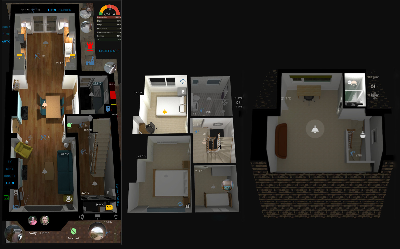
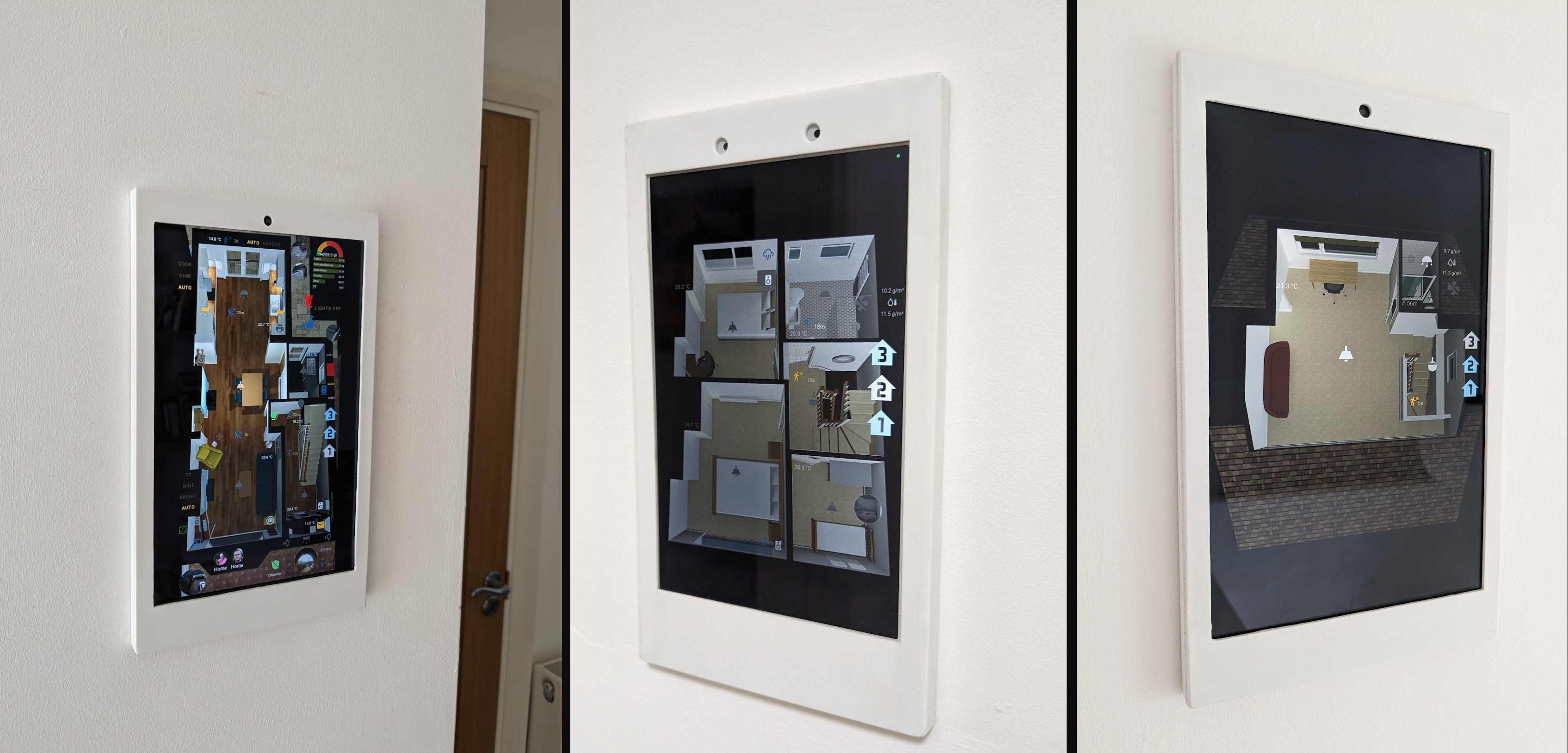
When I open up the Home Assistant app, the main screen is a dashboard containing the floor plans for each of the 3 floors in the house. These floor plans are also displayed by wall-mounted tablets around the house:
Hardware Notes
These tablets are the relatively cheap Samsung Tab A 8” or 10” models, and are all using Fully Kiosk Browser, which I find is well-worth the €8 price tag (I haven’t tried alternatives like Wallpanel.xyz or HAKiosk). Their displays are off most of the time, and are activated by motion, which works quite nicely.
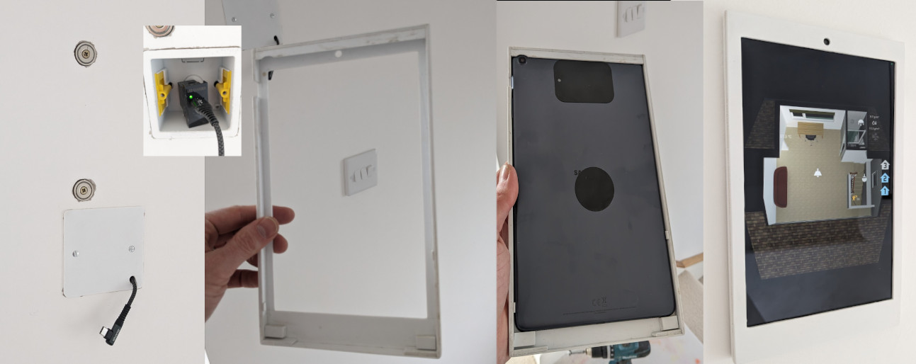
They are all powered by USB routed behind the drywall/plasterboard, using transformer modules like this.
They are hung magnetically. Some 3M thin metal plates mounting are attached to the back of the tablets (the kind you might use with your phone and a magnetic car phone holder), and strong 20mm neodymium ring magnets are fixed in the wall flush to the surface. Two of these magnets are strong enough to hold a tablet in place. This magnetic system makes it easy to pull the tablet off the wall when necessary.
The tablet cases are homemade using styrene sheets, inspired by Adam Savage’s kit bashing videos. They clip in place over the tablet screen, are flush to the wall, and hide the charging cable. They could have been 3D printed instead.
Software Used
Here are the tools I used for this project:
- SketchUp Make 2017. This is the last free desktop version of SketchUp. It is no longer officially offered, but you can find downloads online. Alternatively, you can pay for Sketchup Pro.
- Twilight Render for rendering realistic ray-traced images of sketchup 3D models.
- GIMP or Photoshop for compositing and editing rendered images. I use GIMP below.
- Home Assistant for building the interactive dashboard (using the Picture Elements card).
Originally inspired by
Lukevink’s forum topics from 2020, 3D Floorplan with Hue and Saturation individual, blended RBB Lights and Floorplan with Color synced lights, in which he described how to use CSS transforms to dynamically rendered coloured lighting.
Step 1: Have an Accurate 3D Model
I already had an accurate 3D model of my home, which I had used for various purposes over the years. You will probably have to create your own. The rest of this blog post assumes you used Sketchup to create the model, but you can probably adapt it to other more advanced modelling tools like Blender.
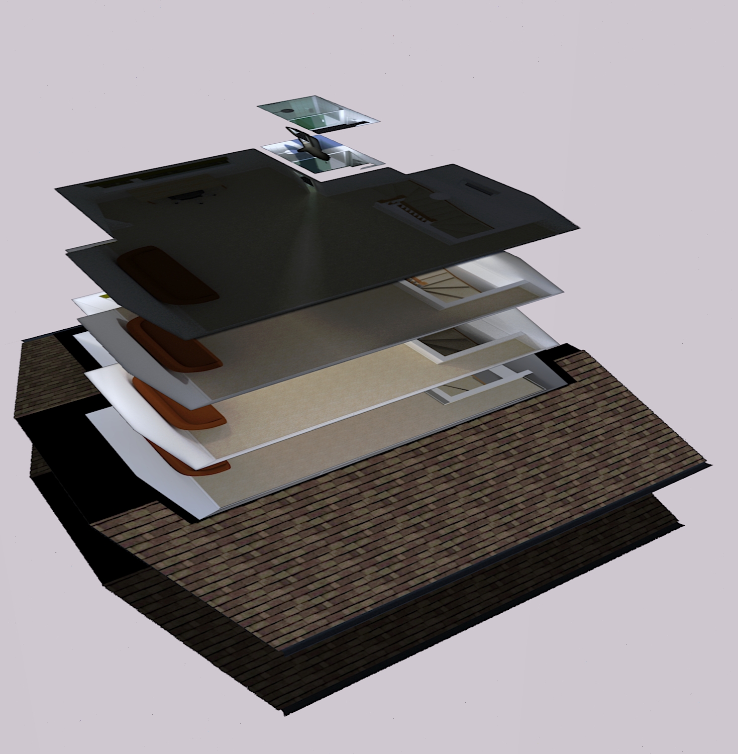
Step 2: Separate Each Floor
I took a copy of the main model and split it up by floor in Sketchup. To split it up:
- Make copy of the model so that you end up with two models of your house side-by-side.
- Position a horizontal section plane just below the ceiling of the floor that you want to render.
- Activate the section plane, and select
Edit>Intersect Faces>With Model. - Deactivate or delete the section plane, switch to parallel projection from the view menu, and select all unwanted geometry in the copy of the house you are working on, and delete it. This should leave just the floor you want to work on exposed.
- Sketchup models are shell-based, so the walls of the floor you just intersected will be hollow when viewed from above. This doesn’t look good when rendered. To fix this, fill in the tops of the walls with rectangles, and make them black or some other solid colour.
- Repeat the above process for each floor of the house. At the end, you should have split your house up into a couple of adjacent models (one for each floor).
Create Scenes
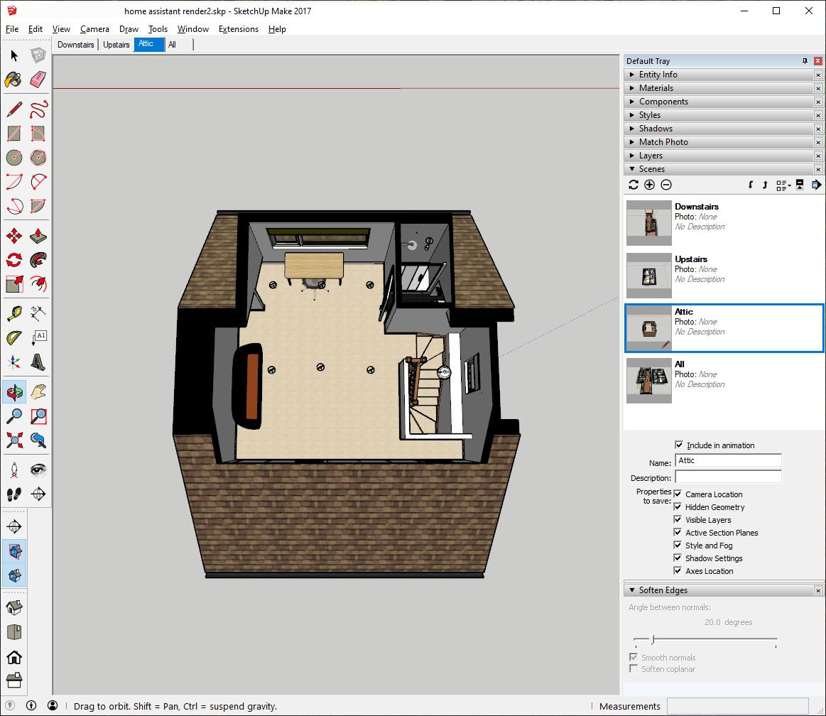
Sketchup scenes allow us to choose a camera position to view each floor from and to hide any unwanted geometry. We can then switch between scenes, and be confident that we are getting exactly the same camera angle each time we return to a scene. This is vital given that we will be rendering out many versions of each floor, which we will superimpose on top of each other later on.
- Use the navigation tools (Orbit, Pan, Zoom) to position the camera and adjust the view of your floor until you have the desired perspective. Try to keep the camera angle consistent so that the final renders of each floor make sense together (and aren’t rotated 90° from each other, for example). If you want the scene to remember a new camera angle you need to click the “update” (🔄) button on the Scenes panel.
- Click on the plus button (⊕) in the Scenes panel to create a new scene.
- Double-click on the scene tab in the Scenes panel to rename it. Choose a descriptive name that helps you identify the view or perspective saved in the scene.
- You can also select any geometry you want to exclude from the scene and hide it. It will only be hidden in this scene.
- Repeat for each floor. For example, I ended up with three scenes: downstairs, upstairs and attic.
Create lights
- Use the light tool icon in the Twilight Render toolbar to create a light for each of your smart bulbs. In most cases I found that a “point” light worked best, which I set to 2600 lumens and approximately 70mm in diameter. You will need to point each of these lights in a direction, which you can do using the “point light” tool or through the menus, and clicking on a point on a surface (e.g., the floor) that the light should point at.
- When you have a number of bulbs that you control together (e.g., in my case 6 GU10 spots in the kitchen) you can copy and paste a twilight light to create clones of it. These show up as a single light that you can switch on or off in the Twilight menus.
- Repeat for every smart bulb in the house.
Render out base images
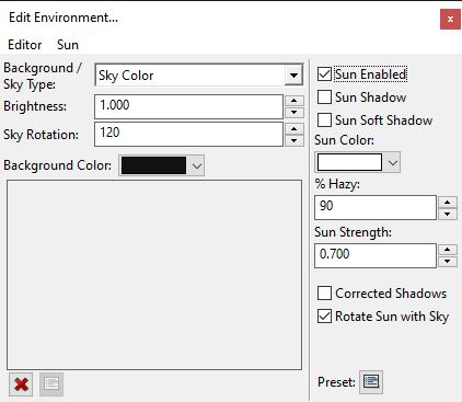
- Click on the “Edit Environment” option in the Twilight menu and configure settings to create some ambient lighting, which floods the model with some base light from all directions (we don’t want shadows being cast by the sun given that the roof is missing!). I used the settings in the screenshot (brightness = 1.0, sky rotation = 120, 90% Hazy and sun strength 0.7).
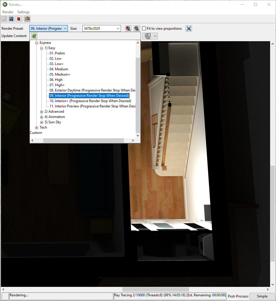
- Now deselect “Sun Enabled” and use Twilight to render out a base image with low ambient lighting, which will represent the scene when it is dark outside an all lights are off. I choose the “High+” quality settings for this. If you choose “Interior” you will get a pitch black render. After the render is finished, save it somewhere with a sensible filename like
floorname_base.png(replace “floorname” as appropriate).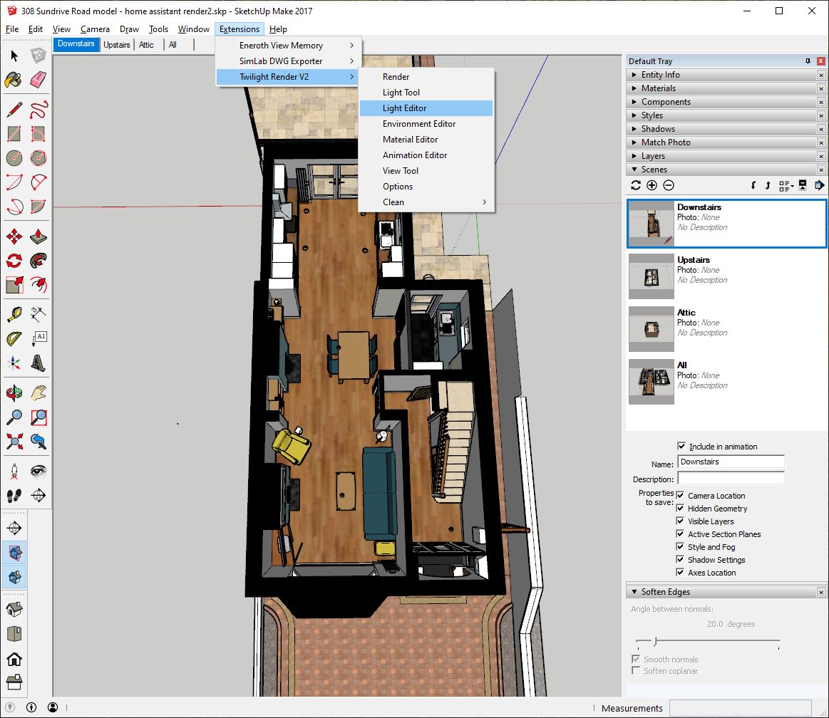
- Use the “edit environment” dialog to re-enable the sun, and re-render the image. This will produce a brighter version, representing the floor with ambient lighting from the sun. We will layer this over the base image later on, and dynamically control its opacity based on how bright it is outside (or what time of day it is, if you like). Save it with a filename like
floorname_ambient.png.
Render out overlay images
Doors & windows
If you want to have any dynamic doors or windows in your scene, you must render new base and ambient images as above, but with each door or window in the alternate position. For example, I created (among others) downstairs_front_door_base.png and downstairs_front_door_ambient.png.
Lighting
- Use the “edit environment” dialog to ensure the sun is turned off.
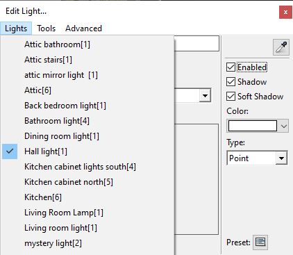
- Select a light using the context menu or Twilight Render toolbar, and switch it on. Make sure no other lights are on (lights that are active are indicated by checkmarks in the Light tool menu).
- Start a render using the “Interior” preset. This will ensure that there is no ambient light in the scene.
- Save the rendered image with a filename like
floorname_lightname.png, e.g.,downstairs_dining_room.png.
Repeat the above process for each light you want to dynamically depict in the final UI. If there are lights in separate rooms that cannot cast light into each other, you can potentially speed things up by rendering them at the same time (they can be split into separate images later on).
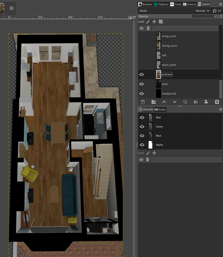
Post-processing in GIMP
We now use GIMP to make any final adjustment to the rendered images. Adjustments we might make include cropping and adjusting brightness and making sure all layers line up properly.
- Use
File>Open as Layersand select all rendered images for a floor. This will create a new image with all the renders as separate layers. - Re-order layers so that dark “base” layer is the bottom layer, followed by the “ambient” layer.
- Hide all layers except for the “base” and “ambient” layers.
- Set the mode of all the lighting layers to
Lighten only. This will only show pixels that are brighter than the underlying layers. - Adjusting the opacity of the “ambient” layer now simulates different amounts of ambient daylight.
- Adjust layers if necessary to make sure they are pixel-aligned with the base layers
- Right click on each layer and select
Add alpha channel - Optionally remove irrelevant parts of lighting layers. You can keep just one room by selecting the room with the scissors select tool, inverting the selection and clearing it (
Edit>Clearor theDELETEbutton), or use the magic wand with a large threshold value (e.g., 20) to select large contiguous unlit areas, and delete them. The areas you remove should now be transparent (thanks to the alpha channel). - Optionally brighten or dim the lighting layers using
Colors>Levels. It is best to do this by changing the input level min/max sliders rather than the mid-point. - Reduce the brightness of the base layer to the level you want to see at night time. It should be bright enough for you to easily identify each room, but dark enough to contrast with any lighting layers that are shown on top of it.
-
Crop the image to the desired size.
-
Multiple independently-controlled RGB lights in one room. Later on we will use CSS transforms to color-shift each lighting layer to represent the current color of the lightbulb. When a room is lit by multiple lighting layers, these color-shifted layers will be overlaid on top of each other, and we will get a better result if we clear any pixels that don’t pertain to the area that it is lighting. Use the select tool with a wide feather to select just the lit area in each lighting layer, invert the selection, and delete everything else.
-
Dynamic doors/windows. If you have a door or window that you want to display in open or closed positions depending on a binary sensor, then you’ll need to prepare a “base” layer and an “ambient” layer for it. For example, when my front door is open, I have a
downstairs_front_door_baselayer displayed above the main base layer, and adownstairs_front_door_ambientdisplayed above the ambient lighting layer (with both ambient layers set to the same opacity). It is best to clear everything irrelevant from these layers by selecting the door/window with the select tool, inverting the section, and clearing it. Use the same selection to clear both the base and ambient layers, so they precisely overlay each other. -
Dynamic doors/windows with dynamic lighting. If you have a dynamic door that may additionally be illuminated by a dynamic light, that’s just one more layer. For example, my front door might be illuminated by the hall light when it is open. So, as well as the
downstairs_front_door_baseanddownstairs_front_door_ambientlayers discussed above, I also have adownstairs_front_door_illuminatedlayer. The latter layer is only displayed when the hall light is on, and has the same CSS transforms applied to it as the hall lighting layer so that it matches. - Before we export everything, review all layers to make sure they are named well and work well. You should be able to toggle visibility and vary opacity to get a preview of the final effect that will be achieved in Home Assistant, as shown in the video below.
- Export the layers as images. GIMP 2 doesn’t support this natively, but you can use the Script-Fu script called “export-layers-plus.zip”.
File>Export Layers..., select a destination, and set the naming template to something likedownstairs_%l.pngto output files with names likedownstairs_dining_room.pngbased on the layer name.
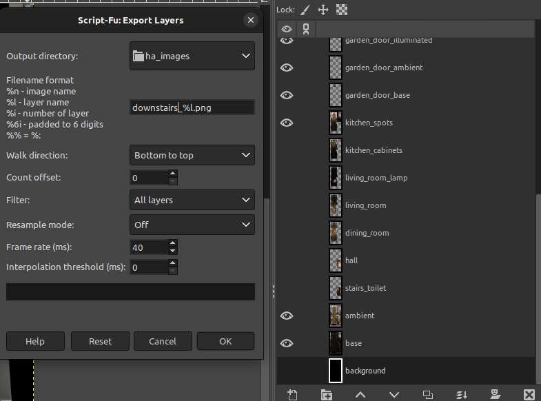
- Move all the final PNG files to a subdirectory of Home Assistant’s
/config/wwwdirectory, so they can be loaded by your browser or Home Assistant app. I placed mine in/config/www/floorplan/images.
Displaying in Home Assistant
The previous steps give us a GIMP file for each floor, with layers representing specific lights and doors. The next task is to get Home Assistant to dynamically display everything to provide a view of the current state of the house. After we do this, the scene displayed by Home Assistant will be dynamically updated with:
- the on/off state of lights
- the brightness of each light
- the hue of any RGB lights
- the current state of doors and windows that you specifically rendered, based on contact sensor state.
We achieve this using the built-in Picture Elements card, which allows us to display an image, and then position other images on top of it, as well things like icons and labels. We use the 3rd party card-mod to allow us to apply custom styles. Card Mod supports templates, which allows us to dynamically adjust the visibility, opacity and hue of layers to reflect the current state of lights, doors and windows.
Basic Picture Element boilerplate
Let’s build up a simple example.
Here’s is a basic use of a Picture Elements to display the background base image, and an overlay “ambient” image:
  - type: picture-elements
    image: /local/floorplan/images/downstairs/base.png
    elements:
      - type: image
        image: /local/floorplan/images/downstairs/ambient.png
        tap_action:
          action: none
        hold_action:
          action: none
        style:
          transform: inherit
          top: 0%
          width: 100%
          mix-blend-mode: lighten
There’s some boilerplate in that code that we’ll need to repeat a lot, and deserves some explaining:
tap_actionandhold_action. This makes the image non-clickable. Without these, your mouse will turn into a pointer whenever it is over any part of the image.transform: inherit. Picture Elements automatically applies atransform: translate(50%, 50%)to all images. This line disables that transform.top: 0andwidth: 100%explicitly position the image at the origin and make it the same width as the base image.mix-blend-mode: lightentells the browser to only render pixels that are lighter than the underlying pixels in lower layers.
Displaying ambient luminosity
Next, we want to make the opacity of the ambient layer dynamic. Although the Picture Elements card allows us to conditionally display elements and CSS rules, this isn’t advanced enough for us. We want the CSS rules themselves to be dynamic, e.g., to vary opacity value of a layer depending on the brightness of a light.
Thankfully Card Mod allows us to specify jinja2 templates, which are evaluated on the server. In the example below, a card_mod section has been added to contain a templated CSS rule to control the image opacity.
  - type: picture-elements
    image: /local/floorplan/images/downstairs/base.png
    elements:
      - type: image
        image: /local/floorplan/images/downstairs/ambient.png
        tap_action:
          action: none
        hold_action:
          action: none
        style:
          transform: inherit
          top: 0%
          width: 100%
          mix-blend-mode: lighten
        card_mod:
          style: |
            hui-image {
              opacity: {{ (0.1 * ([0, states("sensor.driveway_motion_sensor_luminance")|float - 50, 1000.0]|sort)[1]) |string + "%" }};
            }
This approach is based on the examples provided by Ildar_Gabdullin.
Displaying a dimmable light
To add an overlay for a dimmable white smart light, we can add an extra image element like the following, which mostly resembles the “ambient” overlay, but has a different template controlling its opacity.
- type: image
  image: /local/floorplan/images/downstairs/utility_room.png
  tap_action:
    action: none
  hold_action:
    action: none
  style:
    transform: inherit
    top: 0%
    width: 100%
    mix-blend-mode: lighten
  card_mod:
    style: |
      {% set light = 'light.utility_room_light' %}
      hui-image {
        opacity: {{ state_attr(light, 'brightness') / 255 if states(light) == 'on' else '0' }};
      }
Displaying an RGB light
If we want to display an RGB light, we can add a color filter to the style. Replace the card_mod section with something like this:
  card_mod:
    style: |
      {% set light = 'light.dining_room_light' %}
      {% set color = state_attr(light, 'hs_color') or [0, 0] %}
      {% set hue_adj = -28 %}
      {% set sat_mul = 3.0 %}
      hui-image {
        opacity: {{ state_attr(light, 'brightness') / 255 if states(light) == 'on' else '0' }};
        filter: hue-rotate({{ (color[0] + hue_adj)|round(2) }}deg) saturate({{ min(color[1]|round(2) * sat_mul, 100 ) }}%);
      }
Note: I have found that the filter needs the hue to be adjusted by -28° (approximately half a radian?) to reflect what I see in real life. I also multiply the saturation by 3 to exaggerate the effect in the UI. You could also increase the maximum saturation beyond 100% if you like. You may want to play with those numbers.
Displaying a dynamic door or window
The example allows the front door of the house to be shown in the open position depending on the state of the contact sensor installed on the door. We want the way this displays to match the rest of the image, which is also affected by ambient luminosity and the brightness and color of the hall light. To achieve this, there are three layers just for the door, allowing us to apply effects that match the rest of the image.
- A “base” layer, which visually matches the overall base layer.
- An “ambient” layer, which matches the overall ambient layer.
- An “illumination” layer, which matches the layer for the hall light.
All the layers are conditionally displayed depending on the state of the door sensor (via the display CSS rule). The ambient layer opacity is controlled by the ambient luminance, just like the overall ambient layer. The illumination layer has opacity and color controlled by the state of the hall light, just like the respective hall lighting layer.
- type: image
  image: /local/floorplan/images/downstairs/front_door_base.png
  tap_action:
    action: none
  hold_action:
    action: none
  style:
    transform: inherit
    top: 0%
    width: 100%
  card_mod:
    style: |
      {% set sensor = 'binary_sensor.front_door_sensor_open' %}
      hui-image {
        display: {{ 'inherit' if states(sensor) == 'on' else 'none' }};
      }

- type: image
  image: /local/floorplan/images/downstairs/front_door_ambient.png
  tap_action:
    action: none
  hold_action:
    action: none
  style:
    transform: inherit
    top: 0%
    width: 100%
    mix-blend-mode: lighten
  card_mod:
    style: |
      {% set sensor = 'binary_sensor.front_door_sensor_open' %}
      {% set luminance = states("sensor.driveway_motion_sensor_luminance")|float %}
      hui-image {
        display: {{ 'inherit' if states(sensor) == 'on' else 'none' }};
        opacity: {{ (0.1 * ([0, luminance - 50, 1000.0]|sort)[1]) |string + "%" }};
      }

- type: image
  image: /local/floorplan/images/downstairs/front_door_illuminated.png
  tap_action:
    action: none
  hold_action:
    action: none
  style:
    transform: inherit
    top: 0%
    width: 100%
    mix-blend-mode: lighten
  card_mod:
    style: |
      {% set sensor = 'binary_sensor.front_door_sensor_open' %}
      {% set light = 'light.hall_light' %}
      {% set color = state_attr(light, 'hs_color') or [0, 0] %}
      {% set hue_adj = -28 %}
      {% set sat_mul = 3.0 %}
      hui-image {
        display: {{ 'inherit' if states(sensor) == 'on' else 'none' }};
        opacity: {{ state_attr(light, 'brightness') / 255 if states(light) == 'on' else '0' }};
        filter: hue-rotate({{ (color[0] + hue_adj)|round(2) }}deg) saturate({{ min(color[1]|round(2) * sat_mul, 100 ) }}%);
      }
In my home, I have 4 doors and one window cover represented like this.
Finishing touches
Interactive controls
To make the dashboard interactive, we need to add some additional elements to control devices. As you can see from the video at the top of this post, I have icons and labels positioned across the dashboard to control lights, and indicate status of things like current energy, last motion, temperature, humidity and so on. This is all done with regular Picture Elements features.
Variants for tablets etc
I display these floorplans in different dashboards, with some light customisation for different contexts. For example, the home screen on the app is a vertical stack containing the floorplans for each floor of the house, while I have separate dashboards for tablets in various locations that just show the floorplan relevant to those locations. To avoid code duplication, I define the core list of elements for each floor in a single location, and include it from different Picture Element cards.
For example,I have a floorplan/downstairs directory that contains files of this kind of structure:
- type: image
  # ...

- type: state-icon
  # ...

- type: state-label
  # ...
This is then included from different Home Assistant dashboards like this:
- type: picture-elements
      image: /local/floorplan/images/downstairs/base.png
      elements:
        !include_dir_merge_list /config/lovelace/floorplan/downstairs
Responsiveness
I found it tricky to get the labels and icons to display well on screens of different sizes. To keep the icons and labels in a consistent position and size relative to the floorplan, I use the following tricks.
1. Scale icons and labels based on screen size.
I created a CSS file called media-breakpoints.css, which defines a CSS variable called --scaling-factor at different screen sizes in increments of 40px. For example, at 400px wide scaling-factor is defined as 1.0, while at 800px wide it is set to 2.0. You can grab a copy of this file here.
This CSS file is included from the Picture Elements card as follows:
- type: picture-elements
    image: /local/floorplan/images/attic/base.png
    card_mod:
      style: |
        @import url("/local/floorplan/media-breakpoints.css");
    elements:
      !include_dir_merge_list /config/lovelace/floorplan/attic
I then scale icons and labels by adding a CSS transform as follows:
transform: scale(calc(1.0 * var(--scaling-factor)))
The icon or label will then automatically grow or shrink to fit the screen size.
2. Position the centre of icons and labels
The icons and labels now grow and shrink depending on screen size, which makes positioning by their edges inconsistent. Instead, I position each item by its centre, relative to the top-left of the entire floorplan.
Here’s an example of what that looks like:
- type: state-icon
  entity: vacuum.roborock_vacuum_s5
  style:
    transform-origin: top left
    transform: scale(calc(1.0 * var(--scaling-factor))) translate(-50%, -50%)
    top: 81.5%
    left: 56%
- I set the
transform-origintotop left. Position coordinates will now be interpreted relative to the top left origin of the floorplan. transform: ... translate(-50%, -50%)positions the icon so that it’s centre is at the top-left origin of the floorplan. Note that these transformations are applied right to left.top: ...positions the centre of the icon 81.5% of the way down the floorplan.left: 56%positions the centre of the icon 56% from the left of the floorplan.
That’s it
Here are some higher-resolution screenshots of the various floors in my dashboard. I hope you enjoy building something similar.