Low power wake-up receiver for an ESP32 battery-powered project
I am building a battery-powered automatic gate controller, and have been obsessing about battery life. If phase one was building the system, phase two has been about hunting down and eliminating every wasted milliamp. To reduce standby mode current consumption from milliamps to microamps ultimately required fully shutting down the microcontroller during standby, and incorporating a new low-power radio receiver, which allows the system to be remotely activated on-demand. Here’s some detail on that “wakeup receiver”, including the design considerations, component selection and final circuit.
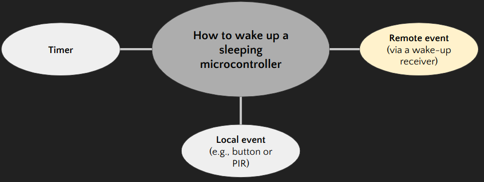
When awake, an ESP32 microcontroller can draw an average of 260mA, and would drain a 2500mAh LiPo battery in less than 10 hours. Therefore, battery-powered microcontrollers need to be designed to sleep most of the time. In deep-sleep an ESP32 uses only 10µA, and would theoretically take 28 years to drain the same battery (here’s a great overview of ESP32 sleep modes). When you put your microcontroller to sleep, you need a way to wake it up again. This usually involves either:
- A timer, e.g., to wake up every 30 seconds.
- A signal on a wire to a RTC GPIO pin. For example, a physical button, or an ultra-low power Passive Infra-Red (PIR) motion sensor (such as the AM312, which consumes only 15µA and is used in this example tutorial).
Sometimes, you want to wake up on demand, e.g., in response to an event that only your IoT server knows about. If running a long wire from your IoT server to your device isn’t part of your design spec, then what you need is a “wake-up receiver” (sometimes abbreviated in the literature to “WuRx” — a pretty unncessary acronym, which I pledge to avoid).
The main problem with wake-up receivers is that you can’t buy them. A web search for wake-up receivers will yield academic and industry papers, but nothing you can order on Digikey or AliExpress. This short paper by Touchstone Semiconductors describes building a passive wakeup receiver as a potential application of the ultra low-power Touchstone TS12011 OpAmp. Unfortunately their design depends on a salvaged super-regenerative receiver from a pre-transistor radio (another thing you can’t buy) and doesn’t discuss the corresponding transmitter, or how to avoid waking up whenever there is radio noise. As of Spring 2023, it seems like wake-up receivers haven’t quite arrived yet. For now, we have to build our own.
Correction, 3 July 2023: @renewaveboard pointed out the in comments of my related Youtube video that RadioControlli makes the €15 RC-WuTRX-434 module, which is a purpose-built wake-up receiver module that uses 130µA in low-power mode.
In principle, there are a few types of wake-up receiver that might be practical to build:
- Acoustic receiver, which listens for a supersonic tone.
- Light receiver - e.g., a photodiode, a light-dependent resistor or a photovoltaic cell, which is activated by a particular wavelength, and a light source such as an IR lamp or laser to activate them. This paper discusses this approach.
- Radio receiver.
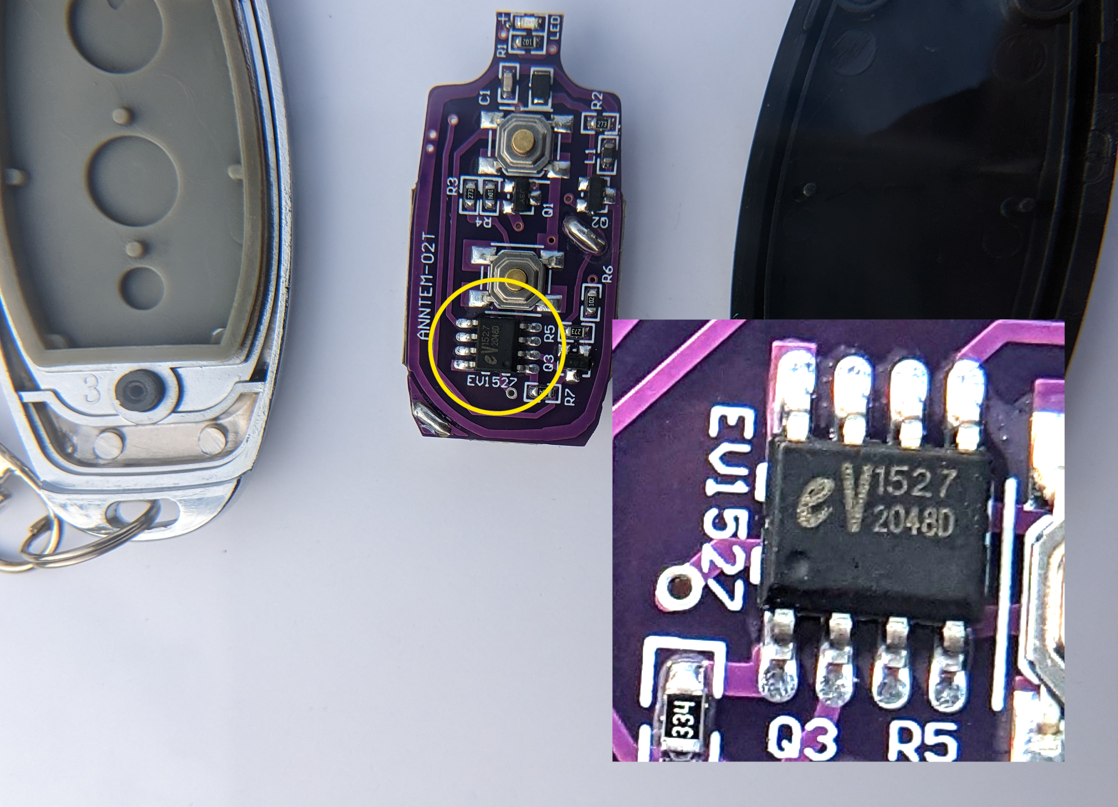
Thankfully, radio receivers already exist that can be adapted to what we need. Most people will already be familiar with keyfob remotes for gates and garage doors. These are usually based on the EV1527 chip (datasheet here), which uses Amplititude Shift Keying to send a transmitter ID and a button ID on 433Mhz or 315Mhz depending on which one you buy. Here’s a good description of how EV1527 remotes work. These have a range of about 25 meters (in my testing up to 30 meters through obstacles), and can form the basis of a short-range RF wake-up receiver.
These remotes normally have a fixed transmitter ID, although RF remotes are available that can clone a remote that you already have. To use these remotes, you need a compatable RF receiver, which you must pair to the remote you intend to use.
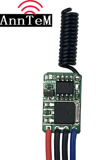
After trawling through AliExpress I eventually found a receiver module made by Anntem that was advertised as being suitable for battery-power, due to an aggressive sleep cycle that yielded low power. It sleeps for 800ms at about 4µA, wakes up for 10ms at 7mA to check for a signal, then goes back to sleep and repeats. This yields an average power consumption of only 100µA. The only downside is that you must hold the button down on your remote for up to 800ms until its signal is received.
This receiver works on 3.5V - 15V and can output up to 2A. When it detects a signal, it connects the blue output lead to VCC. It supports several useful modes that control how long the output will remain switched on. I made a youtube video that demonstrates how to program the mode on one of these receivers by shorting some pads on the PCB and waiting for a specific number of LED flashes, as outlined in the following table:
| Number of flashes | Mode | Primary button function | Secondary button function |
|---|---|---|---|
| 1 | Momentary | Set output to VCC | n/a |
| 2 | Latched | Set output to VCC | Set output to GND |
| 3 | Toggle | Toggle output between VCC & GND | Set output to GND |
| 4 | Latched for 10s | Set output to VCC | Set output to GND |
| 5 | Latched for 30s | Set output to VCC | Set output to GND |
| 6 | Latched for 60s | Set output to VCC | Set output to GND |
| 7 | Latched for 300s | Set output to VCC | Set output to GND |
| 8 | Factory reset |
Simplest Configuration of a Wake-Up Receiver
The simplest way to use this as a wake-up receiver would be to directly power your project through it. It’s wide voltage range and 2A load capacity should allow some easy configurations. For example, a Lithium-Ion Polymer (“LiPo”) battery will deliver more than the required 3.5V over nearly its entire discharge curve (above 0°C at least). This can run the RF receiver, and the blue output lead can pass through a 3.3V linear voltage regulator (e.g., the LD1117V33) and into an ESP32 microcontroller. An even simpler albeit less efficient approach would be to use a regular 5V USB battery pack to power the 5V VIN of an ESP32 devboard via the RF receiver.
The remote could then be used to wake up the project momentarily, or for one of the predefined latched-mode periods (10s, 30s, 60s or 300s). To automatically wake up the system, an EV1527 transmitter module (or a salvaged PCB from a remote) could be hardwired to a permanently-powered ESP32.
I directly wired an ESP32 onto the transmitter PCB pictured above via a small assembly of transistors that shorted one of the transmitter buttons. The transmitter is normally powered by 6V, which I achieved by boosting the ESP32’s VIN output (about 4.5V) with 2 AAA batteries, reaching about 6.5V. Since I now needed to switch a voltage higher than the ESP32’s logic level of 3.3V, I needed to use a combination of an NPN and a PNP transistor, following the comprehensive tutorial here. I noted that I could boost the range by further increasing the voltage to about 8.5V without damaging the transmitter. I also noted that range was optimal when the transmitter is in a horizontal position.
Wake-Up Receiver and Deep Sleep
One downside to the previous configuration is that the ESP32 is completely powered off until the system is explicitly woken up. A refinement is to keep power connected to the ESP32, put it in deepsleep, and to wake it up on a RTC GPIO pin that the RF receiver is connected to. This allows the ESP32 to also wake up based on a timer (or any other local event wired to a GPIO pin). If following this approach, care should be taken to use a voltage divider or similar to reduce the voltage coming from the RF receiver to a safe 3.3V (my reading of table 15 in the ESP32 datasheet is that the maximum permissible voltage is 3.3V + 0.3V = 3.6V).
This review discusses how some ESP32 boards have extremely low power consumption in deepsleep of as little as 11µA. When I implemented this approach using a Firebeetle ESP32-E (one of the very efficient ESP32 boards), I found my standby current was still significantly higher than I expected. After lots of investigating, I found two main culprits:
- The 11µA deepsleep current can be achieved if the board is powered from a 3.3A regulated supply and the “Low-power Solder Jumper Pad” is cut. I was using the 5V input, which meant that the USB driver and the Li-Ion charger were active (here is an excellent and detailed breakdown of Firebeetle ESP32’s power consumption). If you decide to follow this strategy, you need to build a regulated 3.3V supply into your design. Beware of the difference between switching regulators and linear regulators and their implications for efficiency and standby current. See Andreas Speiss’s excellent Youtube video on the topic.
- About 1mA was leaking across the project even when the ESP32 was sleeping. Some of this was due to current leaking across a voltage divider that was used in conjunction with ADC pins, and another 0.5mA was leaking across a relay module and into GPIO output pins in the sleeping ESP32. Fixing the voltage divider leak required adding some switching. I didn’t get to the bottom of this ESP32 GPIO leaks.
Advice
If you choose to follow this approach, one possibility would be to use 3 Lithium batteries to power the project. Two of these in series would provide 3V to power the ESP32 directly, without need for a regulator. An additional battery in series would raise the voltage to 4.5V and power the RF receiver. Arrange some resisters into a 2:3 voltage divider to bring the RF receiver output voltage back down to about 3V before sending it into a GPIO pin. I also suggest carefully monitoring deepsleep current as you hook up the rest of your project so that you can catch any current leaks while they are still simple puzzles to solve.
Achieving Absolute Minimum Standby Current
I eventually decided that it was most important to eliminate all power consumption except for the RF receiver when the project was in standby. This would take care of current leaking across voltage dividers during standby, and would also take care of the unsolved mysteries of current leaking across my relay module and GPIO pins. It would additionally eliminate the 100µA quiescent current consumed by the voltage regulator I was using to supply the ESP32 and other peripherals. To do this, I needed the RF receiver to switch current to all other components. Although the RF receiver would be in charge of switching power on, I wanted to put the ESP32 in charge of when power should be shut off.
The options before me were:
- A relay. The problem was that although the RF receiver could easily drive the relay coil (which needs about 70mA in the case of the SRD-05VDC), this exceeds the max current the ESP32 could supply from a GPIO pin to take over the load and keep the relay latched (table 15 of the ESP32 datasheet indicates 40mA max). If it hadn’t been for this current problem, the 3.3V output from a GPIO pin would have been sufficient to hold an already-latched 12V relay closed, because relay “drop-out” voltages tend to be about 20% of their “pick-up” voltages.
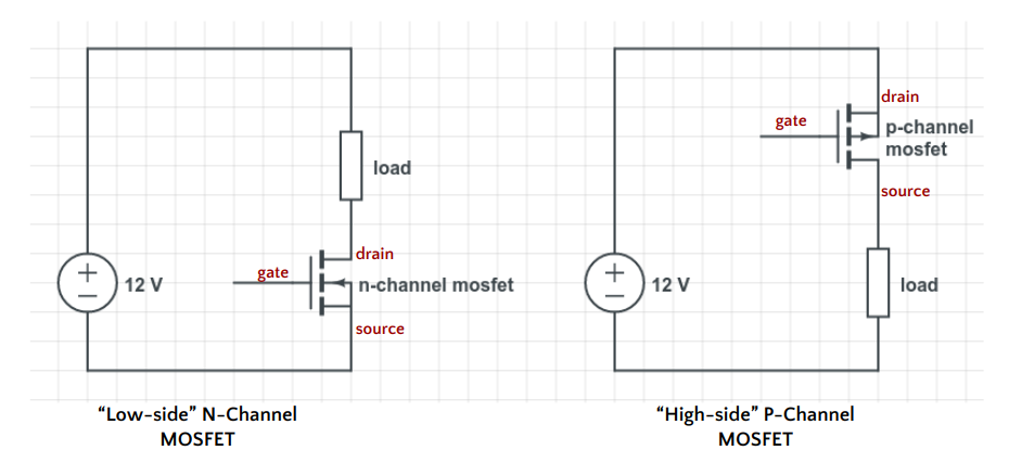
- A P-channel MOSFET. These transistors can be used to switch the “high-side” of a circuit, i.e. they sit between the supply and the load. The gate voltages of P-Channel MOSFETs are the opposite to N-channel MOSFETs, with the MOSFET being “on” when the gate is at 0V, and “off” when the gate is raised above the threshold voltage. Using one would require a voltage to be applied to the gate during standby to keep the MOSFET off, which would have required additional circuitry - perhaps involving an N-Channel MOSFET. In addition, they seem to be less widely used and less well stocked than their N-Channel siblings. I couldn’t find any in stock anywhere that I could deliver to me in a reasonable timeframe.
- An N-channel MOSFET. These can be used to switch the “low-side” of a circuit, i.e., they sit between the load and ground. A wide selection of cheap N-Channel MOSFETs seem to be readily available.
I found the excellent answer here and “MOSFET as a Switch” by ElecronicsTutorials to be very useful resources for understanding the differences between P-Channel and N-Channel MOSFETs.
Since I couldn’t quickly get my hands on any P-channel MOSFETs, I ordered a bunch of N-channel MOSFETs and had them in front of me in less than 24 hours.
Choosing a MOSFET
There are tens of thousands of different kinds of MOSFETs, and it is bewildering trying to figure out how to select one. Here are the criteria I ended up using to narrow it down:
- Type. N-channel enhancement mode is what I was looking for, and is the most widely used type of MOSFET. I didn’t try to figure out how to make things work with depletion mode or P-Channel MOSFETs, but I think it would have been more complicated. The following search criteria also reflect that I was focusing only on N-Channel enhancement mode MOSFETs
- Max/breakdown Vds (drain-source voltage) to ensure it can handle the voltage. In my case, 12V plus a margin.
- Min Vgs(th) (gate-source threshold voltage). This is the voltage necessary to switch the MOSFET. For me, this could be as low as 3.3V so I chose 1V to allow a safety margin.
- Max ID (maximum continuous drain current). This is the maximum current the MOSFET can handle. In my case, I only needed it to energise the relay coil, so 70mA plus a margin (I chose 140mA).
- Mounting type. If you want through-hole, and this narrows the selection significantly.
- In-stock. Does wonders to reduce the choice!
- Packaging type. Are they sold as singles, or in tubes, bags, boxes or on tapes? For me, I needed something I could buy singly or in a small quantity. You can really reduce the selection by eliminating items that are only available of multples of 2500!
- Then sort by price, and start examining the datasheets to make a shortlist. Give preference to low RDS(on) (resistance across the MOSFET when it is on).
I ended up buying a pack of 5 Fairchild FQP30N06L thoughhole n-channel MOSFETs, which have Max Vds=60V, Max ID=32A, Min Vgs(th)=1V-2.5V, are in a convenient TO-220 throughhole package, and were in-stock in my local supplier for about €2 each. More recently, I noticed this particular MOSFET on The Bald Engineer, and I understand it is an example of a “Logic Level” MOSFET because its low Vgs(th) allow it to be switched by a Microcontroller’s 3.3V or 5V.
The dangers of switching shared GND
My first instinct was to use one of the MOSFETs to switch the GND rail that the ESP32, relay board and various other peripherals were connected to. This was a very bad idea, which I luckily survived. It dawned on my that yanking the shared GND in a live circuit with some delicate components might not be a good idea — when GND is cut, electrical charges might start moving in unexpected directions and unexpected voltages:
- perhaps backwards through normally polarized components
- capacitors might discharge high voltages in unexpected directions - perhaps into your microcontroller.
- a voltage divider that normally converts high voltage into a safe 3V for your ESP32’s ADC might suddenly change into a lone resistor sitting between high voltage and your microcontroller’s ADC pin.
I implemented the above for all of 5 minutes, and during those 5 minutes it worked. But I think it would soon have killed the microcontroller had I continued with it.
High-Side Switching with an N-Channel MOSFET and a Relay
My next approach worked well and is the final one in my project. I took a 5V relay from the drawer and used it to switch VCC to the ESP32 and various other peripherals. I then used an N-channel MOSFET to switch the relay, with one end of the relay coil connected directly to VCC, and the other end connected to the MOSFET drain pin.
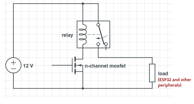
One potential benefit of this approach is that the microcontroller and sundry peripherals (a voltage regulator, a relay board, a ACS712 current sensor and a set of voltage dividers) are physically disconnected during standby.
I connected the RF receiver’s output lead (the blue lead) to the gate of the MOSFET, and could then switch on current across the project by clicking the RF remote button. However, I noticed that the relay would remain latched even after the RF receiver turned off its output signal. This was because the MOSFET gate remained charged, and only slowly and unpredictably discharged (perhaps back via the RF receiver, or internally to the source, or into the air), after which point it would shut off and the relay would disengage. Adding a 10kΩ resistor between the gate and ground allowed the gate to quickly discharge whenever the signal from the RF receiver stopped.
I then connected a GPIO output pin from the microcontroller to the gate (protected by a diode from the relatively high voltage from the RF receiver). Now, both the RF receiver and the ESP32 could drive the MOSFET gate, with the RF receiver charging it initially, and the ESP32 keeping it charged until it is time to go back into standby.
The next problem was that I wanted to use the RF receiver in momentary mode, so that it would only output a signal for as long as the remote button was held down. This would allow things like long presses and double presses to be picked up by the ESP32, which was useful to me. However, with the receiver in momentary mode, power might be switched on and off too briefly for the ESP32 to boot up and take over supplying voltage to the MOSFET gate.
I had noticed that while the MOSFET gate would discharge immediately through the 10kΩ resistor, it took about one second to discharge through a 1MΩ resistor. I could therefore change to a 10MΩ resistor and get about a 10 second grace period before the MOSFET switched off after a momentary pulse from the RF receiver. I also noticed that I could alternatively keep the 1MΩ resistor and add a small 3.3µF capacitor in parallel with the resistor and still get a 10 second delay. This meant that both the MOSFET gate and the capacitor would have to discharge through the resistor before the gate voltage dropped to the point that the MOSFET would switch off. Since I didn’t have any 10MΩ resistors and didn’t want to waste space putting ten 1MΩ resistors in series, I went with the resistor plus capacitor solution.
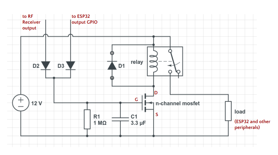 Here we see the discharge resistor
 R1 in parallel with a 3.3µF capacitor, giving about a 10 second discharge time for the MOSFET gate. We also see some diodes:
D1is a flyback diode across the relay coil to deal with any back EMF current produced by the coil’s EM field collapsing when it switches off, potentially damaging the MOSFET.D3protects the ESP32 from the higher voltage that might be applied by the RF receiver to the MOSFET gate.D2isolates the RF Receiver output line from any voltage applied by the ESP32 to the MOSFET gate. This is necessary because I also have the RF Receiver output connected via a voltage divider to a GPIO pin, which allows the ESP32 to directly read the RF signal whenever it is powered on, and I don’t want the ESP32 to detect voltage it is supplying to the MOSFET gate as a signal from the RF receiver.
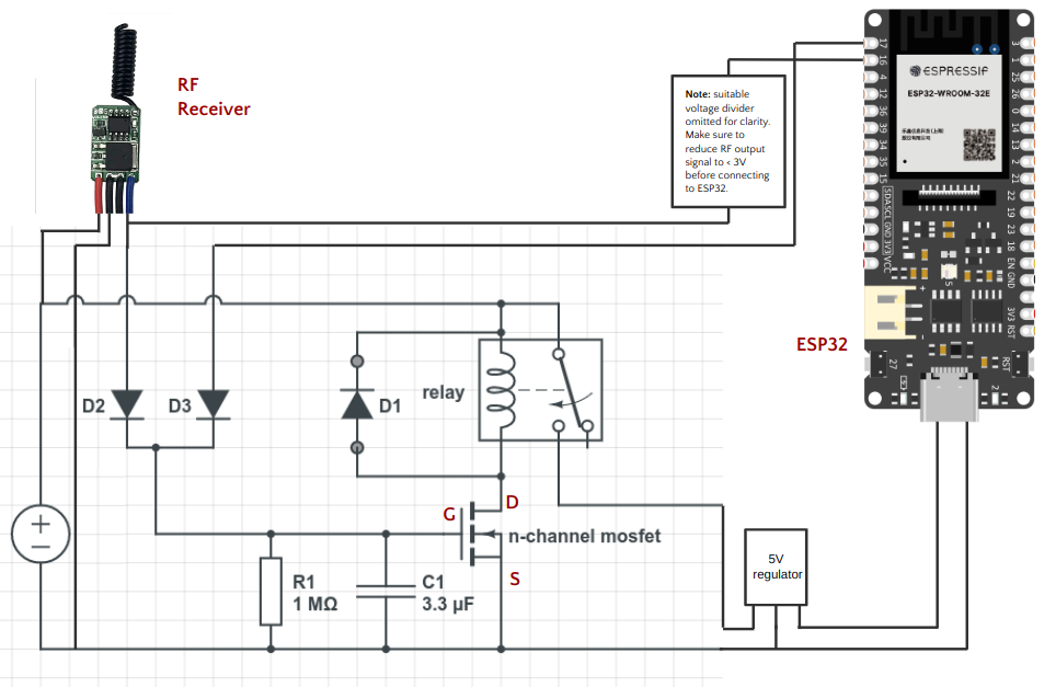
In this diagram we see the circuit along with some other key components: the RF receiver, the ESP32 and a voltage regulator. Some key observations:
- The RF receiver is directly wired to the voltage source, so it is always on (but only drawing an average of 100µA)
- Some 5V peripherals such as an ACS712 current sensor and a relay module board are not shown.
- A voltage regulator is used to create a 5V supply for the ESP32, the relay board (not shown) and the current sensor (not shown). The regulator I chose is the K78L05-1000R3, which is a switching regulator with a high input voltage range of 8-36V, high efficiency (i.e., as a switching regulator it does not simply convert excess voltage into heat) and a very low quiescent current of 100µA. The low quiescent current was originally a priority for me, but ultimately didn’t really matter because the regulator is now switched off whenever the system is in standby. This regulator also comes in a 3.3V version, but I chose the 5V version because I needed to power some 5V peripherals as well as the ESP32. If not for those peripherals I would have gone with the 3.3V version.
- The ESP32’s GPIO pin 17 is connected to the MOSFET gate. As soon as the ESP32 boots up, this pin delivers 3.3V to the MOSFET, which is enough to keep it switched on even after the RF Receiver turns off. When the ESP32 finishes its job it turns off this pin, and within seconds the MOSFET discharges and the relay switches off power.
- GPIO pin 16 is connected to the RF Receiver’s output lead. This allows the ESP32 to read short presses, long presses and double presses as discrete commands. This also works when waking the system up out of standby, thanks to the fast boot time of the ESP32. The ability to wake up the project along with a command can speed up automations (rather than having to wait for it to connect to WiFi) and it also serves as a kind of manual override allowing a user to grab a physical remote and control the project that way. It would also be useful to allow commands to be sent to projects that are out of range of WiFi but still in range for 433Mhz RF.
Summary
The final system consumes only 100µA in standby, giving a standby battery life of several years. It can be woken up by an RF signal at a distance of about 30 meters through brick walls and at least one car. The ESP32 boots in less than 1 second, after which it takes over power control, and is in charge of when the project re-enters standby. The RF signal can be sent automatically via a permanently-powered ESP32 wired to a RF transmitter board, or via a hand-held RF remote. A short 800ms RF pulse wakes up the the project, while a 3 second RF pulse or two 1-second pulses can wake up the project and be simultaneously interpreted as specific commands by the newly-woken ESP32. The components used are cheap and easy to find, add only about 70mA to current consumption of the project when it is active, and were easy to assemble.